Download

1 / 29
290 likes | 475 Views
Advanced beam dynamics experiments at SPARC Alberto Bacci on be half the SPARC group. PITZ Collaboration meeting, 27-28 October 2011, Zeuthen (Berlin). SPARC layout. FLAME laser input line (300TW). New beam lines under installation : Thoson –PWFA – LWFA.

E N D
Advanced beam dynamics experiments at SPARC Alberto Bacci on behalf the SPARC group PITZ Collaboration meeting, 27-28 October 2011, Zeuthen (Berlin)
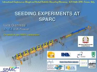
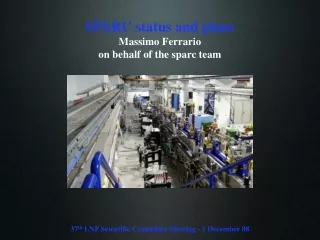
SPARC layout FLAME laser input line (300TW) New beam lines under installation : Thoson –PWFA – LWFA VB cavity for low energy bunch compression and solenoids to emittance compensation seeding laser room seeding line 6 onadulators photocathode laser room Gun 1.6 SW 130MV/m linac -TW S-band
SPARC Velocity Bunching applications Progress towards high brightness beam: -Gun RF pulse shaping 130MV/m (Marco Bellaveglia) -Laser Profile Optimization (Giancarlo Gatti) -Higher thermal Stability C_Band injector FEL Single Spike Velocity Bunching THz Radiation 2 pulses FEL 4 pulses Narrow THz Rad LASER COMB PWFA Thomson LWFA_ext
New RF pulse shaping for Gun feeding • Goals: • Increase the gun accelerating gradient • Maintain the residual phase noise, respect • to the main oscillator, below 100fs • Have abreakdown rate as low as possible • Solution: • In the first 3us the RF level is kept as low as possible to make the PLL (Phase Locked Loop) working • The RF is brought to the maximum level in the last 0.8 us Before (11 MW - 112 MV/m – 4.7 MeV) – 5÷10 discharge per minute Now (14 MW – 130 MV/m – 6.2 MeV) – ~ 1 discharge per hour 10-10torr vacuum level inside the Gun are maintained Marco Bellaveglia, M. Ferrario, A. Gallo, RF pulse shaping optimization to drive low emittance RF photoinjector, to be published
Laser Comb: beam echo generation of a train bunches • - P.O.Shea et al., Proc. of 2001 IEEE PAC, Chicago, USA (2001) p.704. • - M. Ferrario. M. Boscolo et al., Int. J. of Mod. Phys. B, 2006 (Taipei 05 Workshop)
A train of laser pulses at the cathode by birefringent crystal The technique used for this purpose relies on a birefringent crystal, where the input pulse is decomposed in two orthogonally polarized pulses (ordinary, extraordinary) with a time separation proportional to the crystal length. Different crystal thickness are available (10.353 mm in this case). Putting more crystals, one can generate bunch trains (e.g. 4 bunches). The intensity along the pulse train can be modulated (e.g. PWFA) Giancarlo Gatti
Systematic analysis by simulations (two bunches Train) GIOTTO (Genetic Interface for OpTimizing Tracking with Optics) Free parameters (Knobs): Gun ijection phase VB ijection phase Bz field Gun Solenoid Bz field Twcavity N. 1 φgun=11.45 deg px Initial parameters: Tseparation at chathode = 4.27 ps Q = 80 pC + 80 pC σx = σy = 400 μm Twcavity II–III on crest x φgun=36.66 deg px Final Condiction: Tseparation≈ 1 ps current I = current II Minimum rms ε I - II x The minimum total projected emittance (measurable) corresponds to a similar behaviour of both sub-bunches (emittance and current)
Two bunches train caracterization Qt=166 pC (92+78) on crest remarkable agreement Tsep. = 4.27 ps σt-pulses ≈150fs σx = σy = 400 μm εx,y(100%) = 0.8,1.1 mm-mrad, Espread for each pulse < 0.1 % (170 MeV) εx,y (90%) = 0.5,0.5 mm-mrad, σt1 ≈ σt2 ≈ 1ps maximum compression VB phase -90.4 σt=140 fs εx,y(100%) = 4.5,3.3 mm-rad εx,y (90%) = 3.6,2.6 mm-rad Espread 0.4% and 0.25% (110 MeV) Energy separation ≈ 1.5 MeV 350 [A]
Two bunches train caracterization Over-compression VB phase -95.6 σt I =140 fs, σt II =270 fs Tseparation≈0.8 ps εx,y(100%) = 6.2,4.4 mm-rad εx,y (90%) = 5.8,4.0 mm-rad Espread 0.16% and 0.4% Energy separation ≈ 1.2 MeV
FEL Comb at SPARC (two bunches train) From the spectrum dt ≈ 0.615 ps; comparable with data <dt> = 0.8 ps
4-pulses-time-structure time orizontal dim Four pulses COMB structure (200 pC) Laser pulse @ gun cathode whole train length ≈ 9 ps σt(per spike) ≈ 200 fs 4-levels-energy-spectrum longitudinalphasespace vertical dim time energy energy
4 comb pulses and long. phase space rotation Over-compression region: The sub-bunches are well separated; their distance can be controlled by VB phase injection φVB=115.7 deg
4 comb pulses last simulations by Tstep (S1)= -89.5 deg (S1)= -91.5 deg C. Ronsivalle Dog-leg effects are under study
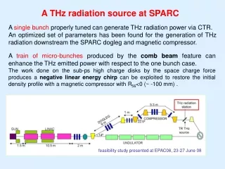
The SPARC THz source – narrow band THz radiation can be easily produced by means of CTR It is difficult to put high charge in sub-ps bunches A laser comb structure in the longitudinal laser profile can solve this problem
The SPARC THz source Martin-Puplet interferometer Silicon Aluminated screen (40 nm coating) • Operating spectral range: 100 GHz-5 THz • It allows to reconstruct the beam profile • First test with pyroelectric detector; foreseen Golay cell or bolometers by Fourier trasforming Interferogram CTR spectrum
Narrow THz radiation measured Interferogram for bunches train show 2N-1 peaks (inter-distance = sub-bunches distance) Radiation spectrum is strongly suppressed outside the comb rep. ferquency Measured Expected Interferogram Spectrum Analysis by Chiadroni
Conclusion • The SPARC linac has improved the machine stability and the gun gradient • We have demonstrated, from experimental point of view, that one can control pulse spacing, length, current and energy separation by properly setting the accelerator. • A very good agreement with simulations
RF Gun feeding schema using an RF switch controlled by a trigger signal coming from the machine trigger distribution, we can decide when the RF level jump takes place. One can decide the power ratio between the two levels combining the DC coupling in the input branch and the value of the fixed attenuation in the low power branch. The phase shifter is used to minimize the phase jump during the switching transition, due to the two different paths of the signal. Marco.bellaveglia@lnf.infn.it
Jitter performance achieved • Time jitter relative to the main RF clock (PLLs ON) • Linac RF devices phase noise (standard phase detection): 40÷100 fsRMS • Photo-cathode LAM measured time jitter (resonant Laser Arrival Monitor): <250fsRMS • e-bunch time jitter • BAM (resonant Bunch Arrival Monitor): <250fsRMS • RF deflector centroid jitter (image analysis): <150fsRMS • Laser amplitude stability (from new timing) • Laser amplification timing locked to machine trigger • Amplitude jitter always <5%
VB Longitudinal compression >> no CSR >> avoid emittance degradation high improving in the bunch’s brightness It permits to reach very high compression (~50 times) Beam executes 1/4 “synchrotron” oscillation in longitudinal phase space. Beam in injected ahead of peak accelerating phase, and compresses as it slips back in phase The VB causes a non-linear longitudinal phase space deformationthat limits the compression capability of the method Cause of deformation is the non-linear RF accelerating fied - S-band (2856 MHz) SLAC type structures A short X-band (11424 MHz)accelerating structure solution
Considering very short bunches the compressing factor can be pushed at higher values; -Short bunches show a lower longitudinal phase space deformation, which isevident directly from analitical considerations Initial debunching: Non-negligible for A=(R/L) >> 1 The first section to compress, the following sections to accelerate and to reduce relative energy spread.
COMPUTED COMPRESSION CURVES OF THE SINGLE BUNCHES OF THE FOUR-PULSES TRAIN Deep over-compression >180 deg Over-compression 180 deg<<90 deg Compression <90 deg 0.0 Deg -105.8 Deg -90.0 Deg =beam rotation in the longitudinal phase space
Operational principle TSTEP simulations
FEL Comb at SPARC - 2 • Along the shift 200 shots have been acquired Simulations agree with the day jitters 65+65 pC, Єx=2.8, γ=232 IV typology of spectrums have been found Only RF def. ; VB phase - 92 Deg Two bunches train