Download
1 / 22
220 likes | 522 Views
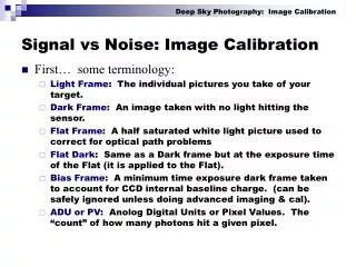
Why Johnson Noise Thermometry (JNT)?. Accurate temperature measurement is required for both control and safetyAll available temperature measurement technologies drift unacceptably under the harsh reactor environmentPeriodic calibration is required to operate with acceptable temperature uncertainty

E N D
1. Continuous Resistance Temperature Detector Calibration Using Johnson Noise Thermometry Presented as part of the IAEA Technical Meeting on Increasing Instrument Calibration Interval Through On-line Monitoring Technologies This presentation conveys the status of Subtask 2.2 � Johnson Noise Thermometer (JNT) Development. David Holcomb is the manager for all subtasks of this DOE International Nuclear Energy Research Initiative project. I am Roger Kisner, the subtask technical leader. Thank you for this opportunity. It is a privilege to be speaking to this group.This presentation conveys the status of Subtask 2.2 � Johnson Noise Thermometer (JNT) Development. David Holcomb is the manager for all subtasks of this DOE International Nuclear Energy Research Initiative project. I am Roger Kisner, the subtask technical leader. Thank you for this opportunity. It is a privilege to be speaking to this group.
2. Why Johnson Noise Thermometry (JNT)? Accurate temperature measurement is required for both control and safety
All available temperature measurement technologies drift unacceptably under the harsh reactor environment
Periodic calibration is required to operate with acceptable temperature uncertainty
Temperature sensor recalibration costs time & money
Recalibration process stresses the sensor and introduces possibility of reconnection error
Johnson noise thermometry is quasi-first principles and consequently is immune to sensor drift
Continuous calibration prevents measurement uncertainty from increasing over time
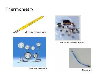
3. Physics Behind the Measurement: a Resistance Generates Thermal Noise Johnson noise is thermal noise
(Nyquist relation) � occurs in all conducting materials and is a consequence of random motion of electrons through a conductor. Each free flight of an electron, between collisions, constitutes a minute current.
The sum of all these currents taken over a long period of time must be equal to zero. But their AC component is Johnson noise.
4. History of Johnson Noise Thermometry For Reactor Temperature Measurement Brixy introduced concept in 1971
ORNL began work for fuel centerline temperature measurement in 1972
U.S., German, and Japanese researchers have implemented JNT in nuclear power plants during the 1980�s & 1990�s
Sensor recalibration & innovative measurement concepts
NASA space reactor program sponsored a �Tuned-Circuit� implementation of JNT at ORNL 1987-91
Cross correlation technique and digital spectrum identification technique initially conceived in early 1990s as part of ORNL SP-100 program
Ongoing International Nuclear Energy Research Initiative (I-NERI) program to develop demonstration version of digital version of JNT incorporating best features of prior work
5. The project participants are from three organizations . The Korean Atomic Energy Research Institute, Ohio State University, and Oak Ridge National Laboratory. The project participants are from three organizations . The Korean Atomic Energy Research Institute, Ohio State University, and Oak Ridge National Laboratory.
6. System Combines Traditional Resistance Thermometry With Noise Measurement Accurate temperature value is obtained by Johnson noise: Requires long term integration. RTD resistance must be accurately measured.
Transfer function produces fast response but subject to drift
Periodically calibrate R/T transfer function with JNT
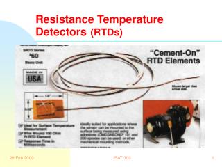
7. Dual Mode JNT Approach Incorporates Resistance Thermometry A standard industrial RTD is the JNT sensor
Resistance measurement performed using a standard bridge circuit
Resistance temperature measurement is essentially prompt
Allows fast response to temperature change
Measurement of any stochastic process takes time with longer times required for more precise measurements
Johnson noise signal from resistance element provides continuous calibration of RTD value � removes drift
Compensation by continuous AC calibration signal eliminates amplifier gain non-linearity and overall spectral response variation � stability assured from preamp input to A/D converter
Small electronics packages � easy mounting, low power consumption, low cost, and high reliability
Digital signal processing � removes environment, electronics, and interconnect noise and monitors instrument status
8. JNT System�s Major Components
9. Why Hasn�t JNT Already Been Widely Adopted? Long, high-capacitance cables alter the transmitted noise
Short cables with local 1st stage amplifier (radiation tolerant electronics may be required)
Periodically measure cable transfer function
The charge thermal motion (Johnson noise) produces a small signal is easily contaminated with other noises
Notably electromagnetic interference and microphonics
Digital signal processing to reject band limited noise was prohibitively expensive until recently
The electronics implementation is challenging
High gain, wide band-width, highly stable devices
Implementing a through-channel in-band calibration check method
10. I-NERI Implementation of Instrument Head
11. Analog Signal Transmission Method Selected To Minimize Radiation Sensitive Technologies In First Stage Amplifier Box Analog signal path
Employs simple front-end electronics
Uses 50 Ohm coaxial cables
two per channel (may use twisted pair style)
Noise channels are at base-band frequency (10MHz BW)
RTD DC resistance is converted to AC signal
Minimizes signal degradation from cable attenuation
Cable attenuation effects compensated by sweep calibration
Amplitude variation effects from cable are cancelled by phase locked loop
Digital signal path configuration rejected because of susceptibility to radiation damage
12. Built and Tested Circuit Board for Dual High-Frequency Preamplifier Channels
13. Built and Tested Circuit Board for DC Resistance, Volt/Freq Converter, and Noise Channel Calibrator
14. Cross Power Spectral Density Employed to Remove Uncorrelated Amplifier Noise Amplifier noise is essentially uncorrelated and increases measurement uncertainty
15. Knowledge of Distribution of Johnson Noise in Frequency Domain Allows Deglitching and Distortion Correction Johnson noise is white while electromagnetic interference tends to be narrowband
Microphonic noise removed by high pass filtering
16. Long Runs of Coaxial Cable Misshapes HF Spectrum
17. Receiver Digitizes, Filters, and Processes The JNT Signals
18. Receiver Subsystem Contains High-Frequency and DC Circuits Johnson Noise Channels
Two wideband amplifier channels
Anti-alias and low frequency rejection filtering (bandpass)
Additional gain (as needed for A/D input)
Analog-to-digital converter
DC Resistance Channel
Noise filtering
Phase-locked loop detector to recover DC signal from frequency encoding
Gain (as needed for A/D input)
A/D Converters (three channels may be card in VME bus)
Power Supply
19. Digital Signal Processing Implemented on Dedicated Hardware at KAERI
20. Digital Signal Processing Calibrate Johnson noise channel
Extract continuous calibration signal
Apply non-linear gain correction to each noise channel using amplitude and harmonic spectral content of calibration signal
Remove unrelated electromagnetic interference signals from Johnson noise signals
Cut spikes
Filter semi-periodic exogenous carriers
Remove amplifier noise from resistance noise by cross-correlation
Calculate absolute reference temperature from processed spectrum
Periodically correct DC resistance measurement by applying absolute reference temperature
21. Conceptual Block Diagram of Digital System Receiver Function
22. Where Do We Go From Here? Plant demonstration
Radiation and temperature hardened system design
Quality control
Testing & more testing
Commercialization