Download
1 / 4
40 likes | 114 Views
Tests of ADC responses. Replaced 20 dB attenuators with 6 dB in two locations to access higher ADC ranges One module/side uplugged, FPHX-1 and FPHX-2 chips exercised. FPHX-1. FPHX-1. 6 dB Atten. FPHX-1. 6 dB Atten. FPHX-2. Extra hits from Poor Pulser Input.

E N D
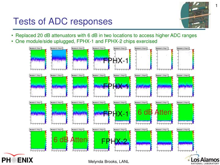
Tests of ADC responses • Replaced 20 dB attenuators with 6 dB in two locations to access higher ADC ranges • One module/side uplugged, FPHX-1 and FPHX-2 chips exercised FPHX-1 FPHX-1 6 dB Atten FPHX-1 6 dB Atten FPHX-2
Extra hits from Poor Pulser Input • Default pulser out of ROC board has some noise pickup which caused triggers on trailing edge of pulse at some amplitudes. Mostly causes extra hits at high amplitude, with wrong BCO • Confirmed hits moved with pulse width. Reducing pulse width removed all these unwanted hits (presumably unable to trigger on trailing edge anymore). See Next slides Calibration Data from module 2, Chip 5, all Channels Extra hits, most at wrong BCO Pulser trailing edge
ADC=0 hits at Largish Amplitudes • Better pulse shape removes trailing edge, bad BCO hits at higher amplitudes • ADC=0 hits are more clearly revealed now (same as Eric found on Xilinx test stand) • No ADC=0 values are found when manually pulse with values = 50, 51, 52, 53, 54, 55, 56… • Manual pulser width = 100 ns, calibration pulser width nominally 800 ns so try 100 ns calibration pulser width (see next) Integrated over all channels in module 2, chip 5. Few ADC=0 hits found Clean BCO Zero-suppressed Some ADC=0 Values
ADC=0 Disappear with Narrower Pulses • 100 ns calibration pulser width. Still not perfect pulse, but better. • ADC=0 values basically gone • Few non-nominal values at low amplitude. All appear to come when pulser amplitude is first switched (first event at a given amplitude) 100 ns