Download
1 / 34
350 likes | 568 Views
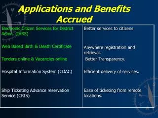
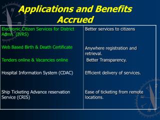
Program Overview. Description. Applications / Customer Benefits. How to Design a System. Product Tips. New Products. 8US Busbar Systems. Space Saving. Cost-effective. Flexibility. 60 mm Busbar System Basics. Systems up to 600 A. Completely compartmentalized

E N D
Program Overview Description Applications / Customer Benefits How to Design a System Product Tips New Products
8US Busbar Systems Space Saving Cost-effective Flexibility
60 mm Busbar System Basics Systems up to 600 A Completely compartmentalized system is more common in Europe Open systems are most common in the U.S Illustration: 3-pole + wiring duct Flat Profile insulating barrier Required by UL in any installation Possible scenario: 3-pole or 4-pole completely compartmentalized system Systems up to 1400 A With “TT” Busbar and busbar holders
Busbar System Components Busbar adapters for individual components Busbar adapters for VL, ED or FXD FBCB Breaker Kits Busbar adapter for complete direct feeders Busbar Adapter and Device Holder for complete reversing feeders
Busbar System Components Terminal Systems w/cover Connection terminals Busbar and Busbar Holders End Covers, Busbar Covers and Cover Profiles PE / N Bus Bar Holders
Technical Data Uninterrupted current for Busbars , E-Cu bare (at air temp. 35 °C in acc. with DIN 43617) Technical data for System
Program Overview Description Applications / Customer Benefits How to Design a System Product Tips New Products
The Fast Bus system Fast Bus is a 3-phase busbar system for power distribution. The modular design provides the flexibility needed to fit your application. Fast Bus also carries domestic and international approvals, which make it ideal for one global panel design. Fastbus helps provide for efficient assembly and simple maintenance, reducing down time.. Adapter shoes can be easily snapped on or removed from the Busbars in seconds and many of the starters and circuit breakers come pre-assembled from Siemens. The Fastbus system can help you save panel space by allowing you to wire and mount circuit protection and motor starters in a tight line. Leave space for future system expansion. Covering all exposed bus bars with the plastic profile.
The Fast Bus system and UL508A “Feeder circuit” is the circuit section located upstream from the last short-circuit-proof element (“short circuit protection device” = SCPD). “Branch circuit” is the circuit section located downstream from the last short-circuit-proof element. When using the Fast Bus busbar system in a power distribution board erected in accordance with UL regulations, it has to be checked whether the application is located in the Feeder or Branch circuit. Components used in the Feeder circuit require larger clearance and creepage distances than in the branch circuit. Clearance and creepage distances in acc. with UL508A in the feeder circuit (rated voltage 251- 600V):
The Fast Bus system • Current Ratings for standard busbar 1) • 5 x 20 mm copper busbar - 362 Amps @ 600V • 5 x 25 mm copper busbar - 432 Amps @ 600V • 5 x 30 mm copper busbar - 500 Amps @ 600V • 10 x 20 mm copper busbar - 564 Amps @ 600V • 10 x 25mm copper busbar – 660 Amps @ 600V • 10 x 30 mm copper busbar - 756 Amps @ 600V • TT Profile copper busbar - 1020 Amps @ 600V 2) • 1) When using 8US1923-3UA01, FBS400F, FBB60F and FBSXPF Busbar Supports at 85°C • 2) When using 8US1943-3AA00 • Bracing ratings 1) • 65kA 3) bracing ratings at 480V at max 600A w/ 24” between supports • 35kA 3) bracing ratings at 600V at max 600A w/ 24” between supports 3) SCCR for 5mm x 20mm and 10mm x 20mm busbars • Factory assemblies for quick installation • SIRIUS 3RA Combination Starters (direct & reversing) up to 75HP @ 460V • Sentron ED & FXD Circuit Breakers (UL489) up to 250A • Customer assemblies for quick installation • SIRIUS 3RA6 Compact Starters up to 20HP @ 480V • Siemens VL: DG, FG, JG, LG Circuit Breakers (UL489) up to 600A ED & FXD 3RA VL 3RA6
Program Overview Description Applications / Customer Benefits How to Design a System Product Tips New Products
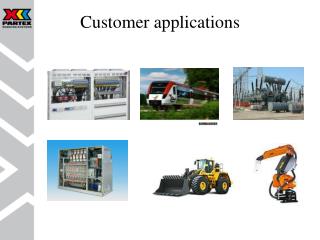
Applications Group Installation according to NEC 430.53 One of the most common uses for Fastbus is multi-motor applications. Fastbus offers a great solution when applied in accordance with National Electric Code section 430.53. We offer a full line of Main Circuit Breakers from 100 A to 250 A mounted on Fastbus shoe adapters. Since our 3RV Motor Starter Protectors are listed for Group Installation they eliminate the need for an additional branch circuit protector for each motor 3RA11 Combination Starters can be used for Single Motor Taps in accordance with NEC 430.53 (D) (3) since the 3RV Manual Motor Controller’s are labeled “Suitable for Tap Conductor Protection in Group installations” as well as Listed for Type E when using the 3RV1928-1H or 3RT1946-4GA07 Busbar cover for covering open Busbar Branch Circuit Breaker for Power Transformer Main Circuit Breaker feeding the Busbar Assembly sized according to NEC 430.52
Applications Ideal for Large Systems The Fastbus System reduces installation time and cost by improving mounting density in panels and speeding up installation time with faster mounting and fewer power connections
Applications Here is a good example of how to control multiple motor loads using Fastbus Multiple Busbar runs can be connected by using any one of six different 3-pole Lug Plate assemblies. (see ratings)
Customer Benefits Initial Build Cost Savings Preassembled starters save labor More condensed panel design Future Expansion Cost Savings Mean Time To Repair Savings Technical Benefits
Commercial Savings: Panel Build Labor • Standard Panel • Install 3 Fuse blocks 1.5 Hours • Install Starters 1.5 Hours • Install Disconnect 0.5 Hours • Install PDB 0.5 Hours • Install Plexiglas 1.0 Hours • Total 5 Hours • SIEMENS Panel • Install Busbars 1.0 Hour • Install Starters 0.5 Hours Install Breaker 0.5 Hours • Total 2 Hours At $30/Hour – Savings of $90 per Panel * Information taken from Customer case study
Commercial Savings: Panel Space Standard Panel SIEMENS Panel * Information taken from Customer case study
Program Overview Description Applications / Customer Benefits How to Design a System Product Tips New Products
How to Configure Fast Bus for Group Installation • Determine Required Load • Select Method to Power Fastbus • Main lug up to 600A • Circuit breakers, 15A to 500A • Select any additional circuit breakers or lugs to feed non-motor loads or motors greater than 100A. • Select 3RA Combination, Compact Starters, or individual starter components for each motor load. • Select Additional Fastbus Adapters for other control components • Determine the required length of busbar based on component widths and plan for expansion space. • Select appropriate length busbar, busbar supports, end covers and any other required components.
Step 1 – Determine total amperage of required loads Due to the nature of Fast Bus, most applications are considered Group Installation per NEC 430-53 Group Installation is an approach to building multiple motor control systems. In Group Installation, multiple motor starters can be grouped under a short circuit protective device. The 3RA Combination Starters have been UL listed for Group Installation in conjunction with Fast Bus. • Review the specification or line drawing to determine all of the loads in the circuit • Use the calculations below to determine the size to the Short Circuit Protective Device Circuit Breaker Selection - Select a circuit breaker (CB) between: Minimum CB size (per NEC430-110) = Sum of all motor Full Load Currents x 115% Maximum CB size (per NEC430-53c) = 250% x FLC of the largest motor + FLC of all other motors Fuse Selection - Calculate the maximum fuse size per NEC 430-53c: Maximum Fuse size = 175% x FLC of the largest motor + FLC of all other motors
Step 2 – Select Method to Power Fast Bus BreakerRatingWidth SCCR 480V FBCB050M 50A 140mm 25kA FBCB060M 60A 140mm 25kA FBCB070M 70A 140mm 25kA FBCB090M 90A 140mm 25kA FBCB100M 100A 140mm 65kA FBCB125M 125A 140mm 65kA FBCB150M 150A 140mm 65kA FBCB175M 175A 140mm 65kA FBCB200M 200A 140mm 65kA FBCB225M 225A 140mm 65kA FBCB250M 250A 140mm 65kA Add “HB” to above (eg. FBCB250M-HB) for High Interrupting versions 100A-250A only. (see next slide) For Short Circuit Protection from 50 to 250A, we recommend using the FBCB***M Main Circuit breakers kits– These circuit breakers have the Fast Bus wires on the load side. Incoming power wires can be fed through the top of the enclosure directly to the line terminals of the circuit breaker. A Rotary or Max-Flex handle operator can be added to disconnect and lock the breaker in the off position. For Short Circuit Protection from up to 500A, we offer the VL Circuit breakers on Fast Bus Adapters – see slide 30 These Fast Bus adapters offer user flexibility in making electrical connections on the line or load side of the breaker. Lug KitRatingWidth SCCR 480V FBT600F 560A 180mm 65kA Feeder Circuit Compliant Other ratings available See page 5/6 of the 2010 Controls Catalog For Short Circuit Protection greater than 500A, use the Three Pole Lug Plate assembly with cover – Provides terminals for the incoming supply from a separately mounted Circuit Breaker or Fuse Block. These lug kits could also be used to jumper from one run of Fast Bus to another. Panel mount circuit breaker or fuse block over 500A
Step 3 – Choosing additional CB’sPre-assembled on Shoes or Kits ready to go Feeder CB Main CB
Step 4 – Select Combination Starters Starter Selection Process Pages 4/38 – 4/41 • Fully assembled Starters: • Non-reversing or reversing motor? • Full Load Current of the motor? • Control Voltage? • Number of auxiliary contacts required on the MSP and on the Contactor? • The 3RA devices can be ordered without any auxiliaries or they can be ordered with one SPDT contact block that plugs into the top front of the MSP and one NO contact block that mounts to the front of the contactor • We recommend using front mount or plug in auxiliary contact blocks to keep the device width to a minimum • Regardless of which version is ordered, additional auxiliary contacts can always be added in the field • These starters can also be built from stock components: • For quick component selection, use Section 4 of the catalog to select a 3RA factory assembled version. To the right of the 3RA catalog number, you will find a list of the components required for field assembly • To see a detailed visual of how to assemble these starters, refer to pages 4/63 through 4/68 of the 2010 catalog. Non-reversingWidth 3RA111 45 mm 3RA112 45 mm 3RA113 55 mm 3RA114 72 mm Pages 4/46 – 4/49 Reversing Width 3RA121 90 mm 3RA122 100 mm 3RA123 120 mm 3RA124 150 mm
Step 5 – Select Additional Fastbus Adapters for other control components The 8US Fastbus system offers Adapter Shoes in various sizes so that you can customize your own Fastbus assembly to your application. Some Adapter Shoes come pre-wired and some without wire so that you can size the wire to your needs or attach to another adapter to mount a connecting device. Adapters for Sirius: 101 (S00)and 102 (S0) frame size 25A rated: 8US1251-5DM07 (45 x 182mm) 8US1250-5AM00 (45 x182mm) 103 (S2) frame size 50A rated: 8US1261-5FM08 (55 x 182mm) 8US1260-5AM00 (55 x 182mm) Long adapter for combination starters: 8US1261-5FP08 (55 x 242mm) 8US1260-5AP00 (55 x 242mm) 104 (S3) frame size: 8US1211-4TR00(70A rated, 72mm x 215mm) FBS10072(100A rated, supplied w/o wires, with DIN, 72mm x 200mm) 8US1251-5DM07 8US1260-5AM00 8US1211-4TR00 Note: It is not recommended to “build your own” circuit breaker assemblies as Siemens offers these as kits that include the appropriate brackets and mounting hardware.
Step 6 – Determine the Required Length of Busbar • Add the widths of all components that will be mounted to the busbar. Including: • End Supports and Intermediate Supports • Main Circuit Breaker or Main Lug Kit • 3RA Combination Starters • Feeder Circuit Breakers • Feeder Lug Kits • Adapters to hold other control products • Determine what additional length may be required for future expansion (if any). • Specify required bracing rating for the system to determine if and how many intermediate supports are required. • Add the widths of all intermediate supports and end supports, which are 21 mm each. • Add all distances together to determine total length of busbar required. • NOTE: • Make sure that the required busbar length will fit in your control panel. If necessary, break the Fast Bus in to multiple runs within the cabinet. When breaking in to additional runs, be sure to add the additional end & intermediate supports and any additional Feeder Lug Kits or Circuit Breakers to your overall length calculation.
Step 7 – Selection of Bus Bar Components • Mounting Components Required for compliance with UL 508A: • 1. Bus Bar End and Intermediate Support • A. 8US1923-3UA01 (bus bar holder support – end & intermediate) • B. 8US1922-1AC00 (end cover) • 2. Busbar Choices: • A. FBB36 / FBB60 • Qty.(3) 36 inches long x 5mm x 20mm Tinned Copper Busbar • Qty.(3) 60 inches long x 5mm x 20mm Tinned Copper Busbar • B. Tin plated Copper Busbar (for bare copper contact Siemens) • 8WC5120 6mm x 6mm x 2m (78.74”) for PE/N application up to 135A • 8WC5053 5mm x 20mm x 2m (78.74”) • 8WC5054 5mm x 25mm x 2m (78.74”) (note: can be double stacked = 660A Ampacity) • 8WC5055 5mm x 30mm x 2m (78.74”) • 8WC5063 10mm x 20mm x 2m (78.74”) • 8WC5065 10mm x 30mm x 2m (78.74”) • 8US1948-2AA00 TT busbar 720mm2 x 2.4m (94.49”) • Optional Components depending on specifications: • Ground Busbar Holder • 8US1923-1AA01 (mounts separately from 8US1923-3UA01 Bus Bar Holder) • Allows use of 5mm x 20mm to 10mm x 30mm busbars as well as 6mm x 6mm busbar • Choice of busbar determines ratings
Program Overview Description Applications / Customer Benefits How to Design a System Product Tips New Products
Changes in Basic Construction to ensure UL508A Compliance • Always specify 8US1922-1AC00 End Cover with 8US1923-3UA01 Busbar Holders. Do not use FBS400F or FBSXPF in new designs. The 8US1923-3UA01 Busbar Holder also acts as the intermediate support. • Always specify 8US1922-2UA01 (Flat Insulator base) • Edge profile is not common in U.S. Do not specify as part of a design if the customer does not request it. • No changes • Do not use the 5SH3532 top cover and 5SH3533 side cover combination which is what is comprised with the FBS400F. This rounded cover is made specifically for mounting the 3 edge profile. See next slide for more detail
Product Tips for UL508 Installations Use Flat Base insulation panel 8US1922-2UA01 Use 3-pole, Busbar Holder for flat busbars 20x5 mm, to 30x10 mm for end and intermediate supports. No top cover req’d. 8US1923-3UA01 Use side cover on end busbar supports for 5-10mm busbars8US1922-1AC00 For “TT” Busbar use: 8US1943-3AA00 Busbar Holder with End Cover Use PE / N Busbar Holder as req’d Mounts separatelyfrom 3-phase holder. Accepts 6x6mm and 20x5 mm, to 30x10 mm busbars 8US1923-1AA01 (new) or 5SH3506 (phase-out) Notes: FBS400F is no longer required to Meet UL508A and will be discontinued. This kit contains the busbar holders, top and side covers. The top cover is intended for accepting the top or bottom edge profiles. FBSXPF is no longer required to Meet UL508A and will be discontinued. This kit contains the intermediate busbar holder and top cover. The top cover is intended for accepting the top or bottom edge profiles.
Product Tips for VL Shoes up to 500A • 8US1213-4AQ03 105mm wide 150A-250A Shoe + hardware for VL DG and FG frame Breaker - Feeder or Main Circuit Breaker. Requires (1) 3VL9300-8SA40 metric mounting screws (4pcs set) to be ordered separately. For FG frame, CB shall not be marked for 100% continuous current. Note: Accepts Max Flex Flange Disconnectsbut requires additional screw set 3VL9300-8SE20. • 8US1213-4AH00 140mm wide 400A-540A Shoe + hardware for VL JG and LG frame Breaker - Feeder or Main Circuit Breaker. Requires (1) 3VL9500-8SA40 metric mounting screws (4pcs set) to be ordered separately. LG frame for use with Elec. Trip unit max rated 400A or for use with thermal MAG trip unit max rated 500A. Note:Accepts Max Flex Flange Disconnectsbut requires two M6 x 120mm screws. Contact Product Management for part number.
Product Tips • 40mm vs. 60mm Designs: • To clarify North American design requirements, 60mm center to center systems are approved in the U.S. whereas 40mm systems are not and are predominantly for European systems. For 40mm system components, refer to the LV1 catalog chapter 17 for Fast Bus. • UL Panel Inspection Update: • The use of Fast Bus components must be described under the Panel Builders Procedure documentation for UL inspection. For all current and future projects, please be sure to provide a copy of the Siemens UL report E160776 Vol 1 Sec 1.
Program Overview Description Applications / Customer Benefits How to Design a System Product Tips New Products
NEW 5SH3538 • 80A Connection Module • Feed components off the bus or another rung of bus bar up to 80A • Wires feed to bottom only • Spring loaded terminals • 3 pole • 16 – 4 AWG cables See page 5/6 of the 2010 Controls catalog
Thank you Busbar Systems SIVACON 8US