Download
1 / 18
240 likes | 271 Views
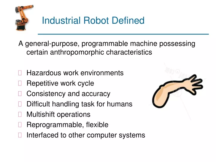
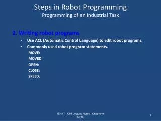
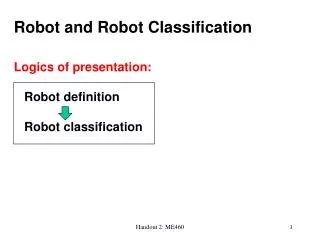
Industrial Robot Defined. A general-purpose, programmable machine possessing certain anthropomorphic characteristics Hazardous work environments Repetitive work cycle Consistency and accuracy Difficult handling task for humans Multishift operations Reprogrammable, flexible

E N D
Industrial Robot Defined A general-purpose, programmable machine possessing certain anthropomorphic characteristics • Hazardous work environments • Repetitive work cycle • Consistency and accuracy • Difficult handling task for humans • Multishift operations • Reprogrammable, flexible • Interfaced to other computer systems
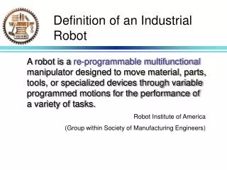
Robot Anatomy • Manipulator consists of joints and links • Joints provide relative motion • Links are rigid members between joints • Various joint types: linear and rotary • Each joint provides a “degree-of-freedom” • Most robots possess five or six degrees-of-freedom • Robot manipulator consists of two sections: • Body-and-arm – for positioning of objects in the robot's work volume • Wrist assembly – for orientation of objects Link3 Joint3 End of Arm Link2 Link1 Joint2 Joint1 Link0 Base
Manipulator Joints • Translational motion • Linear joint (type L) • Orthogonal joint (type O) • Rotary motion • Rotational joint (type R) • Twisting joint (type T) • Revolving joint (type V)
Joint Notation Scheme • Uses the joint symbols (L, O, R, T, V) to designate joint types used to construct robot manipulator • Separates body-and-arm assembly from wrist assembly using a colon (:) • Example: TLR : TR • Common body-and-arm configurations …
Polar Coordinate Body-and-Arm Assembly • Notation TRL: • Consists of a sliding arm (L joint) actuated relative to the body, which can rotate about both a vertical axis (T joint) and horizontal axis (R joint)
Cylindrical Body-and-Arm Assembly • Notation TLO: • Consists of a vertical column, relative to which an arm assembly is moved up or down • The arm can be moved in or out relative to the column
Cartesian Coordinate Body-and-Arm Assembly • Notation LOO: • Consists of three sliding joints, two of which are orthogonal • Other names include rectilinear robot and x-y-z robot
Jointed-Arm Robot • Notation TRR:
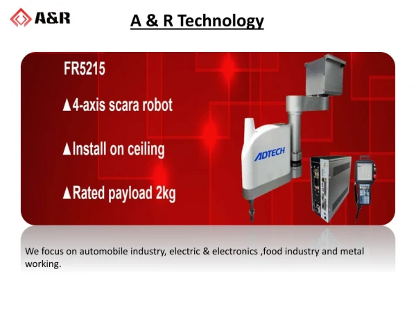
SCARA Robot • Notation VRO • SCARA stands for Selectively Compliant Assembly Robot Arm • Similar to jointed-arm robot except that vertical axes are used for shoulder and elbow joints to be compliant in horizontal direction for vertical insertion tasks
Wrist Configurations • Wrist assembly is attached to end-of-arm • End effector is attached to wrist assembly • Function of wrist assembly is to orient end effector • Body-and-arm determines global position of end effector • Two or three degrees of freedom: • Roll • Pitch • Yaw • Notation :RRT
Example • Sketch following manipulator configurations • (a) TRT:R, (b) TVR:TR, (c) RR:T. Solution:
Joint Drive Systems • Electric • Uses electric motors to actuate individual joints • Preferred drive system in today's robots • Hydraulic • Uses hydraulic pistons and rotary vane actuators • Noted for their high power and lift capacity • Pneumatic • Typically limited to smaller robots and simple material transfer applications
End Effectors • The special tooling for a robot that enables it to perform a specific task • Two types: • Grippers – to grasp and manipulate objects (e.g., parts) during work cycle • Tools – to perform a process, e.g., spot welding, spray painting
Coordinate Systems World coordinate system Tool coordinate system
Robotic Arc-Welding Cell • Robot performs flux-cored arc welding (FCAW) operation at one workstation while fitter changes parts at the other workstation
Industrial Robot Applications • Material handling applications • Material transfer – pick-and-place, palletizing • Machine loading and/or unloading • Processing operations • Welding • Spray coating • Cutting and grinding • Assembly and inspection


![Forecast on China Industrial Robot Industry[2015-2019]](https://cdn4.slideserve.com/7264979/slide1-dt.jpg)