Download
1 / 48
500 likes | 726 Views
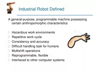
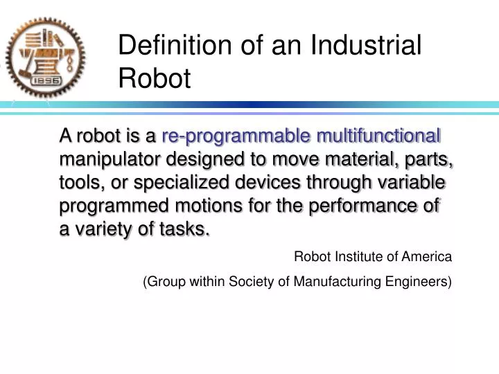
Definition of an Industrial Robot. A robot is a re-programmable multifunctional manipulator designed to move material, parts, tools, or specialized devices through variable programmed motions for the performance of a variety of tasks. Robot Institute of America

E N D
Definition of an Industrial Robot A robot is a re-programmable multifunctional manipulator designed to move material, parts, tools, or specialized devices through variable programmed motions for the performance of a variety of tasks. Robot Institute of America (Group within Society of Manufacturing Engineers)
Components of Industrial Robot • Mechanical structure or manipulator • Actuator • Sensors • Control system
Modeling and Control of Manipulators • Modeling • Kinematics • Differential kinematics • Dynamics
Modeling and Control of Manipulators • Control • Trajectory planning • Motion control • Hardware/software architecture
Mechanical Components • Robots are serial “chain” mechanisms made up of • “links” (generally considered to be rigid), and • “joints” (where relative motion takes place) • Joints connect two links • Prismatic • revolute
“Degrees of Freedom” • Degrees of freedom (DoF) is the number of independent movements the robot is capable of • Ideally, each joint has exactly one degree of freedom • degrees of freedom = number of joints • Industrial robots typically have 6 DoF, but 3, 4, 5, and 7 are also common
Mechanical Configurations • Industrial robots are categorized by the first three joint types • Five different robot configurations: • Cartesian (or Rectangular), • Cylindrical, • Spherical (or Polar), • Jointed (or Revolute), and • SCARA
3-D Homogeneous Transformations • Coordinate transformation (translation+rotation)
3-D Homogeneous Transformations • Homogeneous vector • Homogeneous transformation matrix
3-D Homogeneous Transformations • Composition of coordinate transformations
Euler Angles • Minimal representation of orientation • Three parameters are sufficient • Euler Angles • Two successive rotations are not made about parallel axes • How many kinds of Euler angles are there?
Aim of Direct Kinematics Compute the position and orientation of the end effector as a function of the joint variables
Direct Kinematics • The direct kinematics function is expressed by the homogeneous transformation matrix
Joint Space and Operational Space • Description of end-effector task • position: coordinates (easy) • orientation: (n s a) (difficult) w.r.t base frame Function of time • Operational space • Joint space Prismatic: d Revolute: theta Independent variables
Kinematic Redundancy • Definition A manipulator is termed kinematically redundant when it has a number of degrees of mobility which is greater than the number of variables that are necessary to describe a given task.
Inverse Kinematics • we know the desired “world” or “base” coordinates for the end-effector or tool • we need to compute the set of joint coordinates that will give us this desired position (and orientation in the 6-link case). • the inverse kinematics problem is much more difficult than the forward problem!
Inverse Kinematics • there is no general purpose technique that will guarantee a closed-form solution to the inverse problem! • Multiple solutions may exist • Infinite solutions may exist, e.g., in the case of redundancy • There might be no admissible solutions (condition: x in (dexterous) workspace)
Differential Kinematics • Find the relationship between the joint velocities and the end-effector linear and angular velocities. Linear velocity Angular velocity for a revolute joint for a prismatic joint
Jacobian Computation The contribution of single joint i to the end-effector linear velocity The contribution of single joint i to the end-effector angular velocity
Kinematic Singularities • The Jacobian is, in general, a function of the configuration q; those configurations at which J is rank-deficient are termed Kinematic singularities.
Reasons to Find Singularities • Singularities represent configurations at which mobility of the structure is reduced • Infinite solutions to the inverse kinematics problem may exist • In the neighborhood of a singularity, small velocities in the operational space may cause large velocities in the joint space
Dynamics • relationship between the joint actuator torques and the motion of the structure • Derivation of dynamic model of a manipulator • Simulation of motion • Design of control algorithms • Analysis of manipulator structures • Method based on Lagrange formulation
Lagrange Formulation • Generalized coordinates • n variables which describe the link positions of an n-degree-of-mobility manipulator • The Lagrange of the mechanical system
Lagrange Formulation • The Lagrange’s equations • Generalized force • Given by the nonconservative force • Joint actuator torques, joint friction torques, joint torques induced by interaction with environment
Computation of Kinetic Energy • Consider a manipulator with n rigid links Kinetic energy of the motor actuating link i Kinetic energy of link i
Kinetic Energy of Link • Express the kinetic energy as a function of the generalized coordinates of the system, that are the joint variables
Computation of Potential Energy • Consider a manipulator with n rigid links
Joint Space Dynamic Model Viscous friction torques Actuation torques Coulomb friction torques Force and moment exerted on the environment Multi-input-multi-output; Strong coupling; Nonlinearity
Direct Dynamics and Inverse Dynamics • Direct dynamics: • Given joint torques and initial joint position and velocity, determine joint acceleration • Useful for simulation • Inverse dynamics: • Given joint position, velocity and acceleration, determine joint torques • Useful for trajectory planning and control algorithm implementation
torques Motion control system Trajectory planning system Robot Position, velocity, acceleration Trajectory Planning • Goal: to generate the reference inputs to the motion control system which ensures that the manipulator executes the planned trajectory
Joint Space Trajectory Trajectory parameters in operation space Trajectory parameters in joint space Inverse kinematics algorithm Trajectory planning algorithm Initial and final end-effector location, traveling time, etc. Joint (end-effector) trajectories in terms of position, velocity and acceleration
Point-to-point Motion • Polynomial interpolation • Trapezoidal velocity profile
Motion Control • Determine the time history of the generalized forces to be developed by the joint actuators so as to guarantee execution of the commanded task while satisfying given transient and steady-state requirements
The Control Problem • Joint space control problem Open loop
Independent Joint Control • Regard the manipulator as formed by n independent systems (n joints) • control each joint as a SISO system • treat coupling effects as disturbance
Independent Joint Control • Assuming that the actuator is a rotary dc motor