Download
1 / 10
110 likes | 269 Views
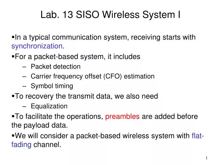
Lab. 13 SISO Wireless System I In a typical communication system, receiving starts with synchronization . For a packet-based system, it includes Packet detection Carrier frequency offset (CFO) estimation Symbol timing To recovery the transmit data, we also need Equalization

E N D
Lab. 13 SISO Wireless System I • In a typical communication system, receiving starts with synchronization. • For a packet-based system, it includes • Packet detection • Carrier frequency offset (CFO) estimation • Symbol timing • To recovery the transmit data, we also need • Equalization • To facilitate the operations, preambles are added before the payload data. • We will consider a packet-based wireless system with flat-fading channel.
Define the packet with the following format : • Preamble: • Each packet has 5 short preambles and 1 long preamble. • Packet format : • Short preamble • Length = 16 samples (for packet detection and CFO estimation) • Long preamble • Length = 32 samples (for symbol timing and channel estimation) S : short preamble L : long preamble S S S S S L Data
Transmitter: Ethernet EMIF RF DAC FPGA PC Digital mod. Add preamble Up- sampling Pulse shaping
Practice 1: • Implement the four modules of the transmitter in Matlab to observe each input/output signal. • Cascade the four modules and observe the input/output signal. • Practice 2: • Implement the four modules with C. • Run the DSP to see if the output signal matches the Matlab result (to/from PC). Ethernet PC Digital mod. Add preamble Up- sampling Pulse shaping
Receiver: SR SR EMIF SR SR OSR SR PC Ethernet Detection Channel est./Equal RF ADC FPGA Packet detection CFO Est./comp. SR: symbol rate OSR: oversampled rate Matching/down sam. Symbol timing
Packet detection: • Calculate autocorrelation of the received signal • Normalize with the signal power: • Decision statistic: • If m(n) exceeds a threshold, a packet is claimed detected.
Example: • D=16、L=16 • Threshold= 0.7 Threshold
Carrier frequency offset (CFO) estimation: • The oscillator frequencies of Tx and Rx are not the same in general. • The downconverted signal: • Then, • Compensation:
Symbol timing: • Cross-correlation of received signal and a known reference signal (preamble) • Example: t(k): a known reference signal
Practice 3: • Implement the three modules in the receiver with Matlab. • Observe each input/output signal. • Cascade the three modules and observe the input/output signal. • Practice 4: • Implement the three modules with C and run the DSP to see the result is the same as that with Matlab.