Download
1 / 16
160 likes | 329 Views
Tens kilowatts power supply based on half-bridge inverter with zero current commutation. A.V. Akimov, A.A. Pachkov.

E N D
Tens kilowatts power supply based on half-bridge inverter with zero current commutation A.V. Akimov, A.A. Pachkov
For the pulse power supply of the VEPP-5 injector klystrons the 40 kW, 50 kV modulators are usedThe modulator’s pulse forming network (PFN) charge is provided by the resonant charging scheme
the resonant charging scheme comprises such bulky parts as the step-up mains transformer (25 kV), the filter capacitor (9 mF, 25 kV), the charging inductor (20 H)
PFN charge voltage depends on the repetition rate of the modulator. At the repetition rate 1 Hz the voltage on PFN decreases to the 70-80 % of the nominal level, it occurs because of the discharge through the leakage resistors of the scheme elements
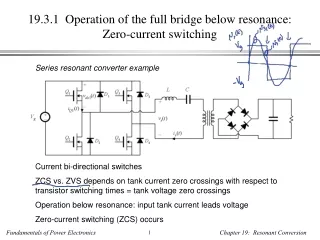
Today the most developed and widespread system providing the capacitive storage devices charge up to the voltages of dozen kilovolts at the power of dozen kilowatts are the power supplies based on the full-bridge serial resonant inverters. The manufacturers of such the power supplies estimate they efficiency at the level 85-92% at the different output power
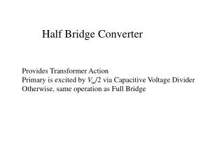
Full-bridge serial resonant inverter The main features of the full-bridge serial resonant inverters are: • - partial charge of the capacitive storage device with the little energy doses which are supplied at the frequency of dozen kilohertz; • - application of the step-up transformer leakage inductance together with the additional capacitor as the elements of the serial resonant circuit; • - use of the four IGBT switches for the full-bridge invertor; • - application of the IGBT’s embedded free-wheel diodes as the essential inverter circuit elements; • - zero current switch turning-on; • - nonzero current switch turning-off at low switch voltage; • - high precision charge stabilization at wide voltage range.
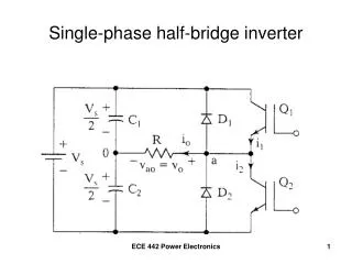
Half-bridge inverter • This topology allows to achieve both the turning-on and turning-off of the switches at the zero current condition. • Half-bridge inverter seems to be preferable due to the only two switch equipment, it lowers both the inverter costs and the switching loses. • Half-bridge inverter operation in the proposed regime does not need the free-wheel diodes employment. • In other respects the half-bridge inverter is similar to the full-bridge inverter.
PS for the 200 keV VEPP-5 electron gun power supply was developed. It has provided 90% efficiency at the 300 W, 3 kV operation
Next PS prototype test stand let us to achieve the 2 kW output power at the 20 kV output voltage
Power module • IGBT half-bridge module SKM300GB125D (Semikron) designed for the 300 A (DC current), 1200 V operation • Polypropylene capacitors K78-21
Driver • Driver is based on the Altera programmable logical integral circuit • Driving algorithm is performed with the IGBT current measurement by the ferrite current transformers. The developed algorithm provides the inverter’s IGBT turning-on/turning-off at the minimal current value (zero-current commutation)
50 kV, 40 kW step-up transformer • The transformer is done with the use of the cores made from the 5BDSR alloy (AMZ, Russia) • The transformer is equipped with the rectifying circuit made with the BYX90G (Philips) diodes • The transformer will be arranged in the oil tank which has the following dimensions: diameter – 480 mm, height – 230 mm
5BDSR alloy • At the transformer rated duty the amplitude magnetic inductance value is expected to be 0.15 T at the maximal voltage frequency 30 kHz. • Outer diameter of the cores is 330 mm, the inner is 190 mm, the core width is 25 mm. • The transformer comprises two such the cores
Electrical strength along the solid dielectric surface • In the quiet homogeneous electrical field (E) the electrical strength along the solid isolator surface is comparable with the electrical strength through the main dielectric body (oil) • There is no the isolator surface extension. The isolator height is equal to the oil isolation gap height (h) • At the windings ends where the electrical field is strong heterogeneous the pure oil isolation is provided
Conclusion • The half-bridge inverter PS prototype test results proved the operation ability of the PS power scheme and the control scheme • It allowed to make precise requirements to the next high-power PS • Today the work on the PS launching on the VEPP-5 modulator is carried on. The next power supply is to provide the 40 kW output power at the voltage 50 kV