Download
1 / 21
210 likes | 310 Views
Problem 1: Vacuum Window. OPTI 523 Laura Coyle, TA January 17, 2014. Design an optical window to a vacuum chamber. Requirements : 2 in diameter clear aperture < λ /2 rms wavefront distortion ( λ = 633 nm) 1 atm pressure on the outside (10 -6 Torr on the inside)

E N D
Problem 1: Vacuum Window OPTI 523 Laura Coyle, TA January 17, 2014
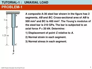
Design an optical window to a vacuum chamber • Requirements: • 2 in diameter clear aperture • < λ/2 rms wavefront distortion (λ= 633 nm) • 1 atm pressure on the outside (10-6Torr on the inside) • Transmit light from 0.6 – 5. µm • Thermal: inside the chamber is ambient temperature • Interface: Mate with a 6” diameter flat stainless steel flange: • 3” ID • 6” OD • 5” diameter bolt circle, 8 bolts, 0.20” clearance holes
Project Schedule • Write the requirements for window. Due 1/24 • Perform preliminary design. • Specify the window, investigate possibilities for procurement • Sketch the geometry • Perform initial calculations to verify design • Define the analysis and design degrees of freedom that must be chosen • Document the preliminary design, but you do not need a complete report • Complete the design. Provide solution as a technical report. Due 1/31 • Design details including drawings for custom parts • Analysis demonstrating performance, survival • Bill of materials • Preliminary fabrication plan
Optical Materials Optical Properties Mechanical Properties CTE Young’s modulus (stiffness) Density Thermal conductivity Specific heat Hardness Climatic resistance • Wavelength range • Refractive index • Dispersion • dn/dT • Quality • Bubbles • Homogeneity • Birefringence
Glass Data Sheets http://www.schott.com/advanced_optics/us/abbe_datasheets/schott_datasheet_all_us.pdf
IR vs. Visible Glasses • IR glasses have significantly higher refractive indices • Visible glass – n ranges between 1.45 and 2.0 • IR glasses – n ranges between 1.38 to 4.0 • Dispersion can be significantly lower (depending on spectral band) • Visible glasses – V ranges from 20 to 80 • IR glasses – V ranges from 20 to 1000 • Many IR glasses are opaque in the visible • And most visible glasses are opaque in the IR • IR glasses are often heavier than visible glasses • IR glasses have significantly higher dn/dT values • Factor of 10 or more higher • IR glasses cost more than visible glasses • by 2 or more orders of magnitude • Significantly fewer number of practical IR glasses than visible glasses
The Glass Map - IR • Larger v, larger n
Designing with IR Glasses Advantages Disadvantages Small choice of glasses Materials are expensive (~1$/gram) One-inch diameter BK7 lens $5 One-inch diameter germanium lens $500 Five-inch diameter sapphire dome = Priceless Some IR materials are difficult to fabricate and/or antireflection coat Fragile, soft, chip easily, low thermal conductivity, etc. Most IR materials have large dn/dT values, so athermalizing can be difficult • Refractive index is usually higher, so fewer lenses are needed to achieve diffraction-limited performance • Most IR materials can be diamond point machined, so aspherics are commonly used in designs • The Airy disk size and diffraction-limited depth of focus are larger for the IR than for the visible, so achieving difraction-limited performance is easier
Mounting Windows • Windows are used in systems that require protection/isolation from the environment • Not supposed to have an effect on light passing through • Design Considerations • Strength • Wedge angle • Surface figure • Sealing • Bowing to pressure/temp differentials • Climatic resistance (AR coating)
Mounting Windows BOND IT CLAMP IT Allows easy separation of constraint and preload Allows disassembly Clamping forces should be controlled Can cause distortions, affect performance Can cause large stresses, affect survivability Can allow for thermal expansion Lens barrels with threaded retainers, consider thread size, assembly torque • One time assembly, difficult to take apart • Easy, stiff in normal direction • Can be compliant in shear direction • CTE differences can cause large stresses, especially for • Large temperature ranges • Large CTE difference • Large dimensions • Use UV curing cement to allow adjustment before curing • Can provide seal • Provides some compliance, mitigates stress from shock loading • Requires careful preparation of surfaces • May require special jigs and procedures • Possibility of outgassing, affecting coatings • Does not require preload
Clamping – Preload Force • Apply force in line with constraint to limit stress, possible distortion, and instability • Analyze shock load: • Force at constraint = Preload Force +/- mass * acceleration • For shock, which is typically given in G’s : • Use mass in kg, 1 G = 9.8 m/s2 get force in N • 1 kg optic that sees 10G shock, Force = 98 kg m/s2= 98 N • Stress = Force/Area • Make sure that applied stress is not so large that it breaks the optic • Rule of thumb for glass, limit short term compressive stress to 50,000 psi • Special calculations to determine stress for point and line contacts • Set preload to maintain contact between the optic and the constraint • Otherwise it can rattle, which causes very high local stress, p
Clamping - Stresses • Calculate preload force • Choose material and thickness to limit stress to < 25% of glass strength (SF = 4) • Increases window thickness a bit doesn’t cost much and provides extra margin
O-rings • Good resource: Parker O-rings • “O-ring Handbook” • Advantages • Don’t require large preload forces • Seal over wide range of temp, pressure, materials • Economical • Considerations for vacuum applications • Outgassing • Size of gland • Surface finish inside gland • Lubrication • Leak rate
Wavefront Deformation - Surface Irregularity • Surface Irregularity weakly couples into transmitted WFE
Wavefront Deformation - Clamping • Stress from clamping causes birefringence – affects transmitted WFE when you care about
Wavefront Deformation – Pressure Differential • Simply mounted circular window with uniform loading
Resources • 521 Notes • Schott website – glass data sheets • Parker o-ring handbook • Schwertz&Burge, Field Guide to Optomechanical Design and Analysis • Vukobratovich notes