Download
1 / 26
260 likes | 389 Views
Tessa Cooper Materials Science and Engineering Rutgers University Advisors: Dr. R. Klie and Q. Qiao Department of Physics, University of Illinois. Methods in Characterizing the GaAs-SrTiO 3 Interface. Overview. Project description. Methods to be used.

E N D
Tessa Cooper Materials Science and Engineering Rutgers University Advisors: Dr. R. Klie and Q. Qiao Department of Physics, University of Illinois Methods in Characterizing the GaAs-SrTiO3 Interface
Overview • Project description. • Methods to be used. • Results obtained for bulk SrTiO3. • Results obtained for SrTiO3/GaAs interface.
Overview of the project • Characterize ultra-thin SrTiO3 film on GaAs using Transmission Electron Microscopy (TEM), Electron Energy Loss Spectroscopy (EELS), and multiple scattering calculations. • Determine the effects of having interfacial O vacancies and Ti diffusion in the substrate. • Evaluate potential uses of this material in electrical and other applications.
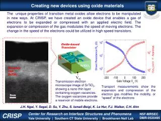
SrTiO3/GaAs (1) As 3d (d) SrTiO3 (4 ML) SrTiO3 (4 ML) SrTiO3/GaAs (2) (c) Ti pre-layer (0.5 ML) Intensity (arb.units) GaAs support GaAs support Ti/GaAs (b) bare GaAs (a) 39 40 41 42 43 44 Energy ( eV ) How are these films made? • Molecular Beam Epitaxy is used to deposit monolayer films of SrTiO3 on GaAs. Sample 2 Sample 1 Ti pre-layer Deposition Direct Deposition R.F. Klie, Y. Zhu, Applied Physics Letters, 87, 143106 (2005).
Schematic drawing of interface: O Ga As Sr Ti 2.0 nm What do the films look like? Highly distinct interfaces are formed, which do not display differences in atomic structure whether or not a prelayer is used. Z-contrast image, SrTiO3 Z-contrast image, SrTiO3 R.F. Klie, Y. Zhu, Applied Physics Letters, 87, 143106 (2005).
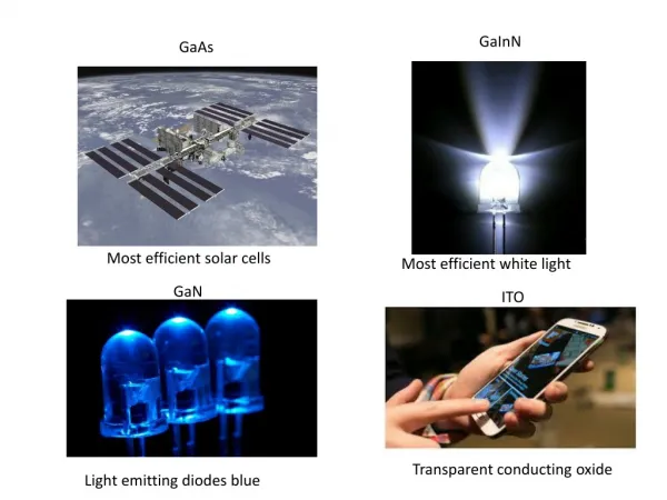
Are the materials important? GaAs • Semiconducting • Highly resistive • High electron mobility • Direct band gap SrTiO3 • Dielectric constant of 300 • Mature deposition method • Good substrate for other oxides. 45° GaAs on (110) plane SrTiO3 on (100) plane
How can this system be used? The properties of this system make it ideal for transistors and other electronic applications. O Ga As Sr Ti • Prelayer • Correct orientation • Minimized defects
What are my project goals? Use image simulations and multiple scattering calculations to model the atomic and electric structures, which helps to… • Interpret experimental results. • Support theories that are not obvious through experimentation.
How do the simulations work? • FEFF9 relies on Full Multiple Scattering calculations to produce x-ray or electron behavior in a material. • Other methods are Fourier based calculations, which require periodic structures.
What do the edges mean? • O electrons are ejected from the K shell, closest to the nucleus. • Ti electrons are ejected from LII or LIII.
What have I accomplished? • Used FEFF9 to produce O K and Ti L edges in bulk SrTiO3. • Constructed GaAs/SrTiO3 interface to use with the multiple scattering calculations. • Used FEFF9 to produce O K and Ti L edges at the interface of SrTiO3. • With Oxygen vacancies • Without vacancies
Construction of Interface As Ti Sr O Ga Targeted a Ti atom at the middle of the interface from which to eject the electron, and removed O atoms around this atom.
Construction of Interface As Ti Sr O Ga Target a specific oxygen atom at the interface, and introduce oxygen vacancies surrounding that atom.
Construction of Interface As Ti Sr O Ga Targeted a specific oxygen atom at the center of the crystal structure, and introduced oxygen vacancies surrounding that atom.
Summary • Bulk SrTiO3 spectra can be reliably calculated for O K edge and Ti L edge. • Vacancy effect occurs in both Ti L edge and O K edge. • Oxygen vacancies can be shown by using FEFF9.
Acknowledgments I would like to thank the following for making this research project possible: The National Science Foundation, EEC-NSF Grant # 1062943 and CMMI-NSF Grant # 1134753. Dr. Jursich and Dr. Takoudis The University of Illinois at Chicago


![SrTiO 3 [010]](https://cdn3.slideserve.com/5554722/slide1-dt.jpg)