Download
1 / 1
10 likes | 143 Views
Dynamic Data Integration and Stochastic Inversion of a Two-Dimensional Confined Aquifer Dongdong Wang 1 , dwang12@uwyo.edu; Ye Zhang 1 , yzhang9@uwyo.edu; Juraj Irsa 1 1 Department of Geology & Geophysics, University of Wyoming, 1000 E. University Avenue, Laramie, WY 82071, USA.

E N D
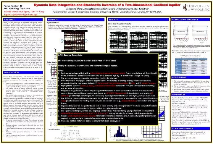
Dynamic Data Integration and Stochastic Inversion of a Two-Dimensional Confined Aquifer Dongdong Wang1, dwang12@uwyo.edu; Ye Zhang1, yzhang9@uwyo.edu; JurajIrsa1 1Department of Geology & Geophysics, University of Wyoming, 1000 E. University Avenue, Laramie, WY 82071, USA Poster Number: 18 AGU Hydrology Days 2013 Matlabshows your figure, "Edit"->"Copy Figure"->paste the figure into ppt No flow METHODS RESULTS COMPUTATION EFFICIENCY ABSTRACT Much work has been done in developing and applying inverse methods to aquifer simulation problems. A new direct inversion method was proposed by Irsa and Zhang (2012) which proved that boundary condition is not required for estimating parameters in small-scale aquifer problems. The scope of this paper is to investigate the applicability of this new method for large simulation problems and to incorporate uncertainty measures in the inversion outcomes. The problem considered is a two-dimensional inverse model (50×50 grid) of steady-state flow for a heterogeneous ground truth model (100 ×100 grid) with two hydrofacies types (Chambers et al. 2000). From the ground truth model, twelve wells were sampled for facies types, based on which experimental indicator histogram and directional variograms were computed. These parameters and models were used by Sequential Indicator Simulation (SIS) to generate 60 realizations of hydrofacies patterns, which were conditioned to the facies measurements at wells. These realizations were further smoothed with Simulated Annealing, before they were conditioned with the direct inversion method to the dynamic data, i.e., observed heads and groundwater fluxes sampled at the same well locations. A set of realizations of estimated conductivities, flow fields, and boundary conditions have been created, which center on the “true” solutions from solving the forward problem with the ground truth model. For conductivity estimation, the estimatedkwas accurate within ±10% of the true values; for boundary condition estimation, the accuracy was within ± 15% of the true values. The inversion system of equations was solved with LSQR (Paige and Saunders 1982) for which we have adopted a matrix scaling preprocessor which speeds up the convergence of the solver by 50 times. Synthetic Model Static Data Integration 1. VariogramModeling Based on Static Hydrofacies Data 2. Sequential Indicator Simulation (SIS) 3. Simulated Annealing Dynamic Data Integration (a) (b) Static Data Integration Results Hydrofacies and error-free hydraulic data observed at 12 sampling wells were obtained from a synthetic model (Fig.1). This model adopted Finite Difference Method (FDM) and MODFLOW 2000 was used as an analysis platform to conduct this FDM model. Sixty realizations were generated by SIS and simulated annealing was used to smooth the resultant images. Image coarsening was adopted to help increase computation speeds on the condition that large-scale hydrofacies continuity was preserved. No flow Time Cost (hours) Grid Size Grid Size Z 300 200 Fig. 5 Computation efficiency comparison between original coefficient matrix and modified coefficient matrix. (a) shows the converge iteration cost and (b) shows the converge time costwith increasing grid discretization. X The modified matrix, while improving the computation performance (Fig. 5), also ensures that the estimated k is correct (Table 1). AGU Poster Template This will be enlarged 200% to fit within the allotted 47" x 68”space. Modify the type size, column widths and banner headings as needed. Note: Each presenter is provided with a 4-foot-high by 6-foot-wide poster board. Poster boards have a 2.5 cm (1-inch) frame. Dimensions of the useable work area are 1.2 meters high by 1.8 meters wide (4′ high x 6′ wide). The presentation must cover the material as cited in the abstract. Place the title of your paper and your paper number prominently at the top of the poster board to allow viewers to identify your paper. Indicate 1) the abstract’s presentation number, 2) title, and 3) authors’ names. Highlight the authors’ names, e-mails, and address information in case the viewer is interested in contacting you for more information. Prepare all diagrams or charts neatly and legibly beforehand in a size sufficient to be read at a distance of 2 meters. Paragraph and figure caption text should be AT LEAST 24-point font (0.9 cm height) and headers AT LEAST 36 point font (1.2 cm height). Use creativity by using different font sizes and styles, perhaps even color. Use different colors and textures/symbols for each line or bar contained in your graph or chart. A serif font (e.g., Times) is often easier for reading main text, and a non-serif font (e.g., Arial or Helvetica) for headers and figure labels. Organize the paper on the poster board so it is clear, orderly, and self-explanatory. You have complete freedom in displaying your information in figures, tables, text, photographs, etc. Use squares, rectangles, circles, etc., to group similar ideas. Avoid cluttering your poster with too much text. Label different elements as I, II, III; or 1, 2, 3; or A, B, C, making it easier for a viewer to follow your display. Include the background of your research followed by results and conclusions. A successful poster presentation depends on how well you convey information to an interested audience. Please do not laminate your poster to ensure that it can be recycled. Fig. 1 The ground truth model (Chambers, Yarus and Hird2000) with a lateral flow boundary conditions . All quantities assume a consistent set of units. High hydraulic head is 300 units, low head is 200 units and the horizontally normal flow path length is 100 units. At each well, 100 hydrofacies, 50 hydraulic heads and 10 fluxes are sampled following a regular pattern. Table 1 The estimated conductivity difference between original coefficient matrix and modified coefficient matrix variogram model(nested model) fitted experimental variogram INTRODUCTION Irsa and Zhang (2012) proposed a new direct inverse method which successfully modeled state variables in an aquifer where boundary conditions are unknown. The following works were completed by them: The new inverse method directly incorporated noisy observed data (hydraulic heads and flow rates) at the measurement points in a single step, without solving a boundary value problem. This method effectively solved small-scale aquifer inversion problems, where hydraulic conductivity spatial distributions are know a priori, which results in a deterministic inverse formulation. The stability and computational efficiency of this method were both proven for the inverse problems at small-scale. However, for large-scale problems in real applications, the hydrofacies distributions are usually unknown and need to be estimated. The computational efficiency of this method also needs to be explored when it comes to large-scale problems. This research will try to address stochastic large-scale aquifer inversion problems without knowledge of boundary conditions, and thus, proving the applicability of the new method mentioned above with necessary modifications and adaptions for stochastic inversion with high efficiency on the two-dimensional confined aquifer. To achieve this goal, hybrid data integration will be required for inverse modeling, including dynamic data, such as hydraulic heads and fluxes, and static data, such as hydraulic conductivities. This study conducted a stochastic static and dynamic data integration follows these steps: Develop a synthetic model to obtain observed data, including static hydrofaices conductivity and error-free dynamic hydraulic data. Generate variogram models based on the static data from the12 sampling wells. Conduct simulated annealing to smooth the images generated by SIS. Conduct aquifer parameter inversion on each smoothed realization. Improve computation performance (speed, stability and accuracy) of the inverse solver. CONCLUSIONS Fig. 2 Experimental variograms based on 12 sampling wellsin horizontal (left) and vertical (right) directions. The estimated k was accurate within ±10% of the true values; for boundary condition estimation, the accuracy was within ± 15% of the true values. The inverse method was proven applicable for integrating static and dynamic data within a stochastic framework. For inverting large problems, however, careful scaling analysis is needed to improve the performance of the iterative solver. Following Chambers et al. (2000), this study encoded the true hydrofacies by 1 (sandy facies) and 0 (clay facies). Based on the indicator histogram and variogram models, SIS is conducted using the GSLIB (Duetschand Journel 2000 ). true head boundary estimated head boundary of a given realization Fig. 3 Stochastic Simulation results via SIS based on the sandy facies (white) and the clay facies (black). Three of the sixty SIS realizations and the corresponding inverted models are presented here, including simulated annealing results and coarsening results. The concept of compactness in topology is adopted to design simulated annealing algorithm applicable to our problem. Dynamic Data Integration Results REFERENCES The 60 coarsened realizations (Fig. 3, bottom row) are inverted based on 600 heads and120 fluxes sample form the 12 wells. Hydraulic conductivity k of the clay hydrofacies (black zones in Fig. 3) is estimated. The k of the sandy facies (white zones in Fig. 3) is obtained by a prior information equation, i.e., kclay/ksandratio is assumed known. Both the estimated conductivity distribution and the inverted hydraulic head boundary condition were compared to the true values, i.e., the solution of Fig. 1. (Fig. 4) • Chambers, Richard L, Jeffery M. Yarus, and Kirk B. Hird (2000), Petroleum geostatistics for nongeostatististicians, The Leading Edge, 19(5), 474 – 479, • doi: 10.1190/1.1438630. • Deutsch, C.V., and A.G. Journel, GSLIB, Geostatistical Software Library and User’s Guide, Oxford University Press, New York, New York, 1992. • Irsa, Juraj, and Ye Zhang (2012), A direct method of parameter estimation for steady state flow in heterogeneous aquifer with unknown boundary conditions, Water Resource Research, 48, W09526, doi:10.1029/2011WR011756. • Paige, Christopher C., and Michael A. Saunders (1982), LSQR: an algorithm for sparse linear equations and sparse least squares, ACM Transactions on Mathematical Software, 8(1), 43-71. Based on the inversion method proposed by Irsa and Zhang (2012), stochastic inversion has been developed. Since this research tried to address large-scale problem, computation efficiency is key. To efficiently solve inversion equations, a linear iterative solver was utilized, i.e., LSQR (Paige and Saunder 1982). Coefficient matrix is modified to improve computation performance, including isomorphism, linear transform and inverse equation simplification. (a) (b) Approximation Function: Simplified (c) (d) ACKNOWLEDGMENTS Continuity Equations: This work was funded by the Center for Fundamentals of Subsurface Flow at the School of Energy Resources at the University of Wyoming. Funding Number: SER 1217-20756-2013 h: hydraulic head x, z: Cartesian coordinates ai: approximated parameter k: hydraulic conductivity δ: weight for continuity equations Fig. 4 (a) Boundary indices shown for the true model (c) Estimated hydraulic conductivity distribution (b) Inverted hydraulic head boundary conditions (d) Relative error of estimated boundary hydraulic heads