Download
1 / 1
10 likes | 177 Views
STUDIES ON HIGH-PRECISION MACHINING AND ASSEMBLY OF CLIC RF STRUCTURES. J. Huopana 1,2 , S. Atieh 3 , G. Riddone 3 , K. Österberg 4,1.

E N D
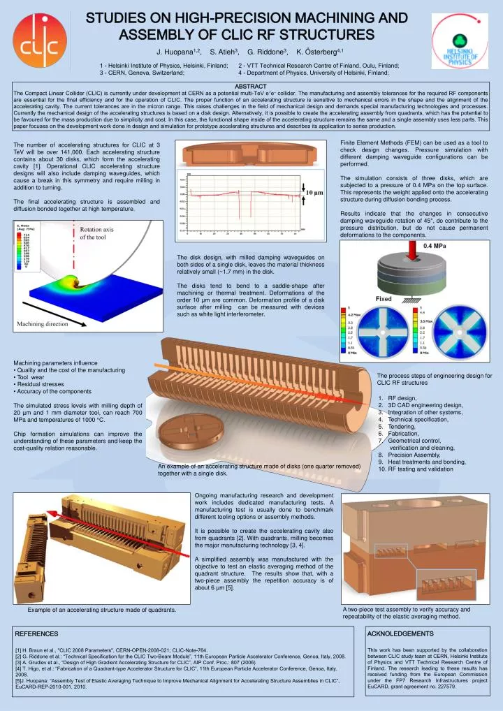
STUDIES ON HIGH-PRECISION MACHINING AND ASSEMBLY OF CLIC RF STRUCTURES J. Huopana1,2, S. Atieh3, G. Riddone3, K. Österberg4,1 1 - Helsinki Institute of Physics, Helsinki, Finland; 2 - VTT Technical Research Centre of Finland, Oulu, Finland; 3 - CERN, Geneva, Switzerland; 4 - Department of Physics, University of Helsinki, Finland; ABSTRACT The Compact Linear Collider (CLIC) is currently under development at CERN as a potential multi-TeV e+e– collider. The manufacturing and assembly tolerances for the required RF components are essential for the final efficiency and for the operation of CLIC. The proper function of an accelerating structure is sensitive to mechanical errors in the shape and the alignment of the accelerating cavity. The current tolerances are in the micron range. This raises challenges in the field of mechanical design and demands special manufacturing technologies and processes. Currently the mechanical design of the accelerating structures is based on a disk design. Alternatively, it is possible to create the accelerating assembly from quadrants, which has the potential to be favoured for the mass production due to simplicity and cost. In this case, the functional shape inside of the accelerating structure remains the same and a single assembly uses less parts. This paper focuses on the development work done in design and simulation for prototype accelerating structures and describes its application to series production. Finite Element Methods (FEM) can be used as a tool to check design changes. Pressure simulation with different damping waveguide configurations can be performed. The simulation consists of three disks, which are subjected to a pressure of 0.4 MPa on the top surface. This represents the weight applied onto the accelerating structure during diffusion bonding process. Results indicate that the changes in consecutive damping waveguide rotation of 45°, do contribute to the pressure distribution, but do not cause permanent deformations to the components. The number of accelerating structures for CLIC at 3 TeV will be over 141,000. Each accelerating structure contains about 30 disks, which form the accelerating cavity [1]. Operational CLIC accelerating structure designs will also include damping waveguides, which cause a break in this symmetry and require milling in addition to turning. The final accelerating structure is assembled and diffusion bonded together at high temperature. The disk design, with milled damping waveguides on both sides of a single disk, leaves the material thickness relatively small (~1.7 mm) in the disk. The disks tend to bend to a saddle-shape after machining or thermal treatment. Deformations of the order 10 µm are common. Deformation profile of a disk surface after milling can be measured with devices such as white light interferometer. • Machining parameters influence • Quality and the cost of the manufacturing • Tool wear • Residual stresses • Accuracy of the components • The simulated stress levels with milling depth of 20 µm and 1 mm diameter tool, can reach 700 MPa and temperatures of 1000 °C. • Chip formation simulations can improve the understanding of these parameters and keep the cost-quality relation reasonable. The process steps of engineering design for CLIC RF structures 1. RF design, 2. 3D CAD engineering design, 3. Integration of other systems, 4. Technical specification, 5. Tendering, 6. Fabrication, 7. Geometrical control, verification and cleaning, 8. Precision Assembly, 9. Heat treatments and bonding, 10. RF testing and validation An example of an accelerating structure made of disks (one quarter removed) together with a single disk. Ongoing manufacturing research and development work includes dedicated manufacturing tests. A manufacturing test is usually done to benchmark different tooling options or assembly methods. It is possible to create the accelerating cavity also from quadrants [2]. With quadrants, milling becomes the major manufacturing technology [3, 4]. A simplified assembly was manufactured with the objective to test an elastic averaging method of the quadrant structure. The results show that, with a two-piece assembly the repetition accuracy is of about 6 µm [5]. A two-piece test assembly to verify accuracy and repeatability of the elastic averaging method. Example of an accelerating structure made of quadrants. ACKNOLEDGEMENTS REFERENCES [1] H. Braun et al., "CLIC 2008 Parameters", CERN-OPEN-2008-021; CLIC-Note-764. [2] G. Riddone et al.: “Technical Specification for the CLIC Two-Beam Module”, 11th European Particle Accelerator Conference, Genoa, Italy, 2008. [3] A. Grudiev et al., “Design of High Gradient Accelerating Structure for CLIC”, AIP Conf. Proc.: 807 (2006) [4] T. Higo, et al.: “Fabrication of a Quadrant-type Accelerator Structure for CLIC”, 11th European Particle Accelerator Conference, Genoa, Italy, 2008. [5]J. Huopana: “Assembly Test of Elastic Averaging Technique to Improve Mechanical Alignment for Accelerating Structure Assemblies in CLIC”, EuCARD-REP-2010-001, 2010. This work has been supported by the collaboration between CLIC study team at CERN, Helsinki Institute of Physics and VTT Technical Research Centre of Finland. The research leading to these results has received funding from the European Commission under the FP7 Research Infrastructures project EuCARD, grant agreement no. 227579.