Download
1 / 30
320 likes | 358 Views
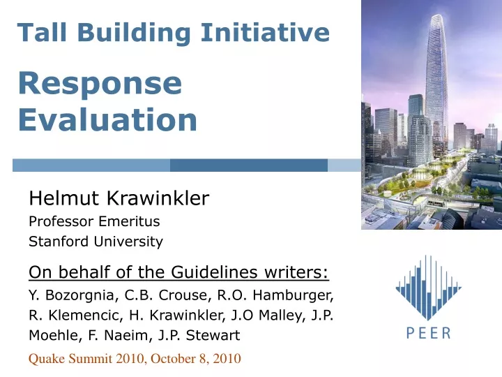
Tall Building Initiative Response Evaluation. Helmut Krawinkler Professor Emeritus Stanford University On behalf of the Guidelines writers: Y. Bozorgnia, C.B. Crouse, R.O. Hamburger, R. Klemencic, H. Krawinkler, J.O Malley, J.P. Moehle, F. Naeim, J.P. Stewart.

E N D
Tall Building InitiativeResponse Evaluation Helmut Krawinkler Professor Emeritus Stanford University On behalf of the Guidelines writers: Y. Bozorgnia, C.B. Crouse, R.O. Hamburger, R. Klemencic, H. Krawinkler, J.O Malley, J.P. Moehle, F. Naeim, J.P. Stewart Quake Summit 2010, October 8, 2010
Performance Objectives • Demonstrate that structure will be capable of essentially elastic response and limited damage under Service-level Earthquake shaking (mean RP = 43 years = 50/30) • Demonstrate, with high confidence, that structure will respond to Maximum Considered Earthquake (MCE) shaking • without loss of gravity-load-carrying capacity • without inelastic straining of important lateral-force resisting elements to a level that will severely degrade their strength; and • without experiencing excessive permanent lateral drift or development of global structural instability.
MCE Level Evaluation • Objective: provide, implicitly, adequate life safety protection • Protection against collapse • Protection against life threatening falling hazards • Protection against aftershocks & condemnation • Use 3-D nonlinear response history analysis – for at least 7 ground motion pairs • Use a realistic model of the structural system • Follow capacity design principles (enforced in acceptance criteria) • Minimum base shear not required
Acceptance Criteria at Component Level • Force-controlled actions with severe consequences: Fu≤ fFn,e • Fu = smaller of • 1.5 times mean • Mean + 1.3s but ≥ 1.2 times mean • Fn,e = nominal strength based on expected material properties • f = resistance factor
Acceptance Criteria at Component Level • Deformation controlled actions: No specific limitations, but use realistic model of component behavior, including deterioration, or limit maximum deformation to a conservative (low) value du. If d > du in any one analysis: • Strength in this action should drop to zero • Effect on related strength properties should be evaluated
Acceptance Criteria at System Level Mean of max. transient drift in every story ≤ 3.0% Max. transient drift in every story ≤ 4.5% Mean of max. residual drift in every story ≤ 1.0% Max. residual drift in every story ≤ 1.5% Loss in story strength at max. drift should not be more than 20%
System Modeling Issues • Incorporate all components and all behavior modes (e.g., shear in RC) that “significantly” affect prediction of seismic response • Might require post-analysis review and re-analysis • Flexibility of floor diaphragms should be modeled if deemed important • Analysis should provide information needed to quantify diaphragm forces • Podium and backstay effects must be represented realistically • P-Delta effects must be included • Include real torsion, but no requirement for accidental torsion
Wall Hinging at the Base gy=Vy/W Loading Story Shear Story OTM
NRHA force demands may be very different from elastic “expectations” Maximum moment in shear wall
NRHA force demands may be very different from elastic “expectations” Maximum shear force in shear wall
Component Modeling Deterioration in strength and stiffness must be considered if it significantly affects the response of the structure to the MCE ground motions Or – conservative estimates must be made of strength and deformation capacities
Basic Observation The cyclic envelope curve is different from the monotonic backbone curve
Resource DocumentATC-72-1 Interim Guidelines on Modeling andAcceptance Criteria for Seismic Design andAnalysis of Tall Buildings
Resource DocumentATC-72-1 • GENERAL MODELING ISSUES • Types of Models • Deterioration • P-Delta effects • Damping • Uncertainties • PROPERTIES OF NONLINEAR STRUCTURAL COMPONENTS • Steel beams and columns • Steel panel zones • Axially loaded steel braces • RC beams, columns, and joints • PLANAR AND CORE WALL SYSTEMS AND COMPONENTS • Planar walls, flanged walls, core walls • Coupling beams • Slab-columns and connections • FLOOR DIAPHRAGMS, COLLECTORS, AND PODIUM AND BACKSTAY EFFECTS • Rigid, semi-rigid, and flexible diaphragms • Podium and backstay effects
Use of Strain-based Models (Fiber & Curvature Models) Argument for their use: whenever lumped plasticity models are not available • Columns subjected to biaxial bending and large axial force • Shear walls with (and without?) openings • Spandrel beams?
Use of Strain-based Models (Fiber & Curvature Models) Arguments against their use: RC: • Rebar buckling? • Rebar fracture? • Bond slippage and pullout? • Shear? Steel: • Local instabilities? • Fracture? • Joint panel zones? Need to account for cyclic deterioration
Use of Concentrated Plasticity (Spring) Models Rotational spring models if inelastic behavior mode is bending Translational spring models if inelastic behavior mode is shear Arguments for their use • Can capture deterioration characteristics if good calibrations are available from experimental data • Are relatively simple Arguments against their use • Are approximate • Not available for many important failure modes
ASCE 41 models may be used if deemed appropriate • They were intended to be used in conjunction with pushover analysis • They were not intended to be used for hysteresis modeling • The sharp drop from C to D is not representative of reality • except for brittle failure modes • They may not be applicable to many “new” components
F c F K y s K pc k F = F r y K e d d d d y c r u d d p pc Component Models with Deterioration (see ATC-72) 1.Monotonic (initial) backbone curve: F d • Cyclic deterioration parameter • Description of hysteresis loops Q-HYST Degrading Stiffness Flag-Shaped Bi-Linear Hysteresis
Option 1 Modeling Option #1 – ATC-72 Use of monotonic backbone curve and explicit incorporation of cyclic deterioration
Option 2 Mod. B.C. from exp. env. curve Modeling Option #2 – ATC-72 Use of cyclic envelope curve as modified backbone curve, and no incorporation of cyclic deterioration – limit du to max. observed in test
Modeling Option #3 – ATC-72 Use of factors to generate modified backbone curve from monotonic backbone curve, and no incorporation of cyclic deterioration - capping strength Fc* = 0.9 Fc - plastic deformation capacity dp* = 0.7dp - post-capping deformation capacity dpc* = 0.5dp - residual strength Fr* = 0.7Fr - ultimate deformation capacity du* = 1.2dc
Option 3 Mod. B.C. from Monotonic B.C Modeling Option #3
Option 4 Modeling Option #4 – ATC-72 No deterioration at all in analytical model ultimate deformation capacity du* corresponding to 80% of capping strength on descending branch of Options 2 or 3
Option 1 Option 2 Mod. B.C. from exp. env. curve Option 3 Option 4 Mod. B.C. from Monotonic B.C Comparison of ATC-72 Modeling Options
Penalties for Options 3 and 4 q 1.5 c q pu Modified backbone curve, Option 3 M c Initial backbone curve 0.8M c q q ’ =0.7 p p Ultimate rotation, Option 3 Ultimate rotation, Option 4 q q q ’ q y 0.5 c c pc q q p pc
What is new? • No radical changes • Explicit formulation of performance objective and acceptance criteria at two levels of ground motions (SLE & MCE) • Consideration of deterioration in component properties – if it is important • Or acceptance of “penalty” in component modeling • Consistent design and performance evaluation process