Download
1 / 42
460 likes | 687 Views
Explore the principles of dispersion in optics, from angular to linear dispersion, through prisms, diffraction gratings, and echelle gratings. Learn about resolving power, spectral resolution, and the role of monochromators.

E N D
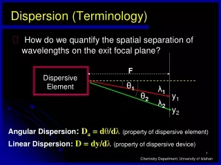
Dispersion (Terminology) • How do we quantify the spatial separation of wavelengths on the exit focal plane? F Dispersive Element θ1 λ1 θ2 y1 λ2 y2 Angular Dispersion: Da = dθ/dλ(property of dispersive element) Linear Dispersion:D = dy/dλ(property of dispersive device) Chemistry Department, University of Isfahan
D = F × Da More Dispersive Terminology • If dθ is small, it can be shown that: • More commonly, we will use: • Reciprocal Linear Dispersion(D-1) = 1/D • -typically around 0.1 - 20 Å/mm in UV/Vis • Effective Bandwidth: Sin d = d = dy/F D-1 = 16 Å/mm w = 100 μm Δλeff = 1.6 Å Δλeff = D-1 × w Slit-width Chemistry Department, University of Isfahan
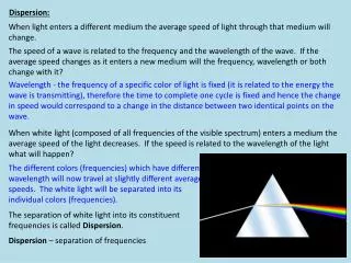
Prism • As we saw in the previous chapter, refraction of light is given by Snell's law:n1 sin θ1 = n2 sin θ2 A prism is a transparent optic that is shaped to bend light. Since the refractive index of a material varies with wavelength, prisms are useful for dispersing different wavelengths of light. Chemistry Department, University of Isfahan
Dispersion of white light by a prism Incident White light Dispersed light Chemistry Department, University of Isfahan
Dispersion by a prism (a) quartz Cornu types and (b) Littrow type Chemistry Department, University of Isfahan
Rainbow Chemistry Department, University of Isfahan
Diffraction Gratings • Typically, a series of closely spaced facets ruled onto a reflecting surface • Spacing of facets must be comparable to λ of EMR • Parallel EMR rays striking adjacent facets will travel different distances • Constructive interference occurs if the difference in the distance travelled by the two rays is an integer multiple of λs • Constructive interference will be a function of the angles (incident and reflection) and the wavelength Chemistry Department, University of Isfahan
d Let’s see how it works! Grating normal Diffraction beam at Reflected angle r 1 Monochromatic Beam at incident Angle i 2 3 3 2 r i 1 D C Wave front B A Chemistry Department, University of Isfahan
Dispersion by Echelle Grating Echelle grating: i = angle of incidence; r = angle of reflection; d = groove spacing. In usual practice, i r = = 6326. Chemistry Department, University of Isfahan
Echelle Grating • Provides high dispersion and high resolution • Difference with echellette grating • Its blaze angle is significantly greater • The short side of the blaze is used rather than the long side which is used in echellette grating • The grating is relatively coarse, having typically 300 or fewer grooves per mm for UV radiation • The angle of reflection r is much higher in the echelle grating than the echellette and approaches the angle of incidence i, r i = Chemistry Department, University of Isfahan
Echelle Grating • Under these circumstances, the Equation we obtained for echellette grating, i.e. with respect to becomes and the dispersion which was becomes nλ = d[sin(i) +sin(r)] r i = nλ = 2d sin Chemistry Department, University of Isfahan
Comparison of Performance Characteristics of a Conventional and Echelle Grating Chemistry Department, University of Isfahan
Performance Specifications The dispersion is usually given in nanometers per millimeter, where the slit width is expressed in mm. stray light: light transmitted by the monochromator at wavelengths outside of the chosen wavelength and bandpass. high efficiency: maximize the ability to detect low light levels. Resolution is usually of secondary importance since emission spectra rarely have peaks with linewidths less than 5 nm. Chemistry Department, University of Isfahan
Da wavelength independent Dispersion for a Grating • For a fixed angle of incidence (i): nλ = d [ sin (i) ± sin (r) ] n dλ = d cos(r) d(r) So: If the angle r is kept small (<5o): Chemistry Department, University of Isfahan
Dispersion of Grating Monochromators Angular dispersion: Linear dispersion: F: focal length of the monochromator Reciprocal linear dispersion D-1 Chemistry Department, University of Isfahan
Dispersion of Grating Monochromators • What is the role of D-1 in wavelength separation? • D-1 ↓resolution ↑ • or • D-1 ↑ resolution ↑ • What are the effects of d, n and F • on resolution? Chemistry Department, University of Isfahan
Resolution Resolution is the separation of wavelengths in a spectrum. Chemistry Department, University of Isfahan
SpectralResolution/Resolving Power • We define Resolution (or Resolving Power): R = λavg/Δλ Chemistry Department, University of Isfahan
Resolving Power for aGrating • So, in order to just resolve these two spectral lines: λ1 = 4501 Å λ2 = 4499 Å • We need an instrument with a resolving power of: • R = 4500/2 = 2250 • The resolving power of a diffraction grating: R = nN No. of grating blazes illuminated by radiation Spectral Order Chemistry Department, University of Isfahan
Monochromator Slits and Resolution Illumination of an exit slit by monochromatic radiation 2at various monochromator settings. Exit and entrance slits are identical. Reciprocal linear dispersion dl D-1 = dy Dleff = w D-1 Slit width Chemistry Department, University of Isfahan
Illumination of an Exit Slit l3 l1 l2 Monochromator Exit slit Power • l3 l2 l1 • Wavelength Detector
Slit width= 3(l2-l1)/4 Slit width= Slit width= (l2-l1)/2 Slit width= l2-l1 Effective bandwidth Power • l3 l2 l1 • Wavelength
Effect of Slitwidthon Spectrum (Benzene) Chemistry Department, University of Isfahan
Slit width • The slit widths are generally variable, and a typical monochromator will have both an entrance and an exit slit. • The light intensity which passes through a monochromator is approximately proportional to the square of the slit width. • Larger slit widths yield increased signal, what about resolution? Chemistry Department, University of Isfahan
How it all fits together • Suppose we want to “just resolve” the following • Iron doublet: • λ1= 3099.90 Å R= 3099.935/0.07 • λ2= 3099.97 Å = 44,000 Suppose that we have a 100-mm wide grating ruled with 1200 grove/mm ; it has a first-order resolving power of: R = nN = (1)(100 mm)(1200 gr/mm) R = 120,000 Chemistry Department, University of Isfahan
But, can we really resolvethe two lines? • Consider, now, the dispersion of the • monochromator in which that grating is located: • D-1= 16 Å/mm • In order to just resolve the two lines: • Δλeff = 0.07 Å • This requires a slitwidth of: • Δλeff = D-1 × w • w = 0.07 Å/16 Å/mm = 0.00438 mm • w ≈4 μm Chemistry Department, University of Isfahan
How Can WeImprove Resolution? • Decrease Slitwidth (w) • -limits light throughput • Operate in Higher Spectral Orders • -limits light throughput (decreased efficiency) • D-1∝1/n • Increase Focal Length • -limits light throughput (inverse square law) • D-1∝1/F Chemistry Department, University of Isfahan
Optical instrument Five components 1. a stable source of radiant energy 2. a transparent container for holding the sample 3. a device that isolates a restricted region of the spectrum for measurement 5. a signal processor and Fiber Optics 4. a radiation detector Chemistry Department, University of Isfahan
Detectors for spectroscpic instruments , nm 100 200 400 700 1000 2000 4000 7000 10,000 20,000 40,000 VAC UV VIS Near IR IR Far IR Spectral region Detectors Photographic plate Photomultiplier tube Phototube Photon detectors Photocell Silicone diode Charge transfer detector Photoconductor Thermocouple (voltage) or barometer (resistance) Golay pneumatic cell Thermal detectors Pyroelectric cell (capacitance) Chemistry Department, University of Isfahan
Radiation Detectors • Detectors convert light energy to an electrical signal. • In spectroscopy, they are typically placed after a wavelength separator to detect a selected wavelength of light. • Different types of detectors are sensitive in different parts of the electromagnetic spectrum. Chemistry Department, University of Isfahan
Ideal Detectors • high sensitivity • high S/N ratio • constant response over a considerable range of • fast response • minimum output signal in the absence of illumination (low dark current) • electric signal directly proportional to the radiation power ? S =kP + kd dark current radiation power (intensity) Chemistry Department, University of Isfahan
Types of radiation detectors Two major types: one responses to photons, the other to heat • photon detectors: UV, visible, IR • (when used for 3 µm or longer , cooling to dry ice or liquid nitrogen is necessary to avoid interference with thermal signal) • signal results from a series of individual events • shot noise limited • thermal detectors: IR • signal responds to the average power of the incident radiation • thermal noise limited Chemistry Department, University of Isfahan
Photon detectors (a) Photovoltaic cells: radiant energy generates a current at the interface of a semiconductor layer and a metal; (b) Phototubes: radiation causes emission of electrons from a photosensitive solid surface; (c) Phtomultiplier tubes: contain a photoemissive surface as well as several additional surfaces that emit a cascade of electrons when struck by electrons from the photosensitive area; (d) Photoconductivity detectors: absorption of radiation by a semiconductor produces electrons and holes, thus leading to enhanced conductivity; (e) Silicon photodiods: photons increase the conductance across a reverse biased pn junction. Used as diode array to observe the entire spectrum simultaneously • Multichannel photon detector Chemistry Department, University of Isfahan
Barrier Layer Cell Thin layer of silver Glass Selenium Plastic case Iron - +
Vacuum Phototubes • The number of electrons ejected from a photoemissive surface is directly proportional to the radiant power of the beam striking that surface; • As the potential applied across the two electrodes of the tube increases, the fraction of the emitted electrons reaching the anode rapidly increases; • when the saturation potential is achieved, essentially all the electrons are collected at the anode. • The current then becomes independent of potential and directly proportional to radiation power. Chemistry Department, University of Isfahan
Cathode Wire anode 90 Vdc
Photomultiplier Tube (PMT) • Photomultiplier Tubes (PMTS) are light detectors that are useful in low intensity applications such as fluorescence spectroscopy. • Due to high internal gain, PMTs are very sensitive detectors. • PMTs are similar to phototubes. They consist of a photocathode and a series of dynodes in an evacuated glass enclosure. • Photons that strikes the photoemissive cathode emits electrons due to the photoelectric effect. Chemistry Department, University of Isfahan
Photomultiplier Tube (PMT) • Instead of collecting these few electrons at an anode like in the phototubes, the electrons are accelerated towards a series of additional electrodes called dynodes. • These electrodes are each maintained at a more positive potential. • Additional electrons are generated at each dynode. Chemistry Department, University of Isfahan
Photomultiplier Tube (PMT) • This cascading effect creates 105 to 107 electrons for each photon hitting the first cathode depending on the number of dynodes and the accelerating voltage. • This amplified signal is finally collected at the anode where it can be measured. Chemistry Department, University of Isfahan
+ _ Dynode Potential(V) Number of electrons 1 90 1 5 2 180 10 7 3 3 270 100 4 6 4 360 103 2 1 5 450 104 8 6 540 105 9 7 630 106 Quartz envelope Anode Grill 8 720 107 9 810 108 Photoemissive Cathode Anode 900V Gain =108 900V dc Photoemissive Cathode Dynodes 1-9 Anode To readout