Download
1 / 19
190 likes | 196 Views
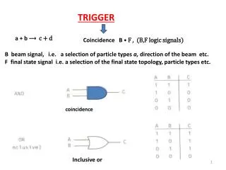
DT Trigger links. Outline: From local trigger to Sector Collector From Sector Collector to Regional Trigger. DT front end Barrel. Server Board. DT Sorter. DT Track Finder. DT trigger links layout. Detector in UXC. LVDS link: Ethernet cables FTP cat. 6. rate 480 Mbps @ max 40 m.

E N D
DT Trigger links • Outline: • From local trigger to Sector Collector • From Sector Collector to Regional Trigger F. Odorici - INFN Bologna
DT front end Barrel Server Board DT Sorter DT Track Finder DT trigger links layout Detector in UXC • LVDS link: • Ethernet cables FTP cat. 6. • rate 480 Mbps @ max 40 m Trigger Boards (BTI,TRACO,TSS) C C B Minicrate LVDS copper link Towers in UXC Sector Collector Opto link • Opto-link: • multimodal fibers 850 nm • 1.6 Gbps @ 100 m Counting room in USC GLOBAL MUON TRIGGER F. Odorici - INFN Bologna
Trigger Server to SectorCollector LVDS link • For each Trigger Server use a unique stream for & : • - 80 bits (2 tracks)/BX @ 40 MHz • LVDS link on < 30m shielded copper cable: • 2 cables/minicrate (Ethernet class 6 FTP, 4 pairs/cable) • Chipset from National Semiconductors: • Serializer 10-to-1 DS92LV1021 (8 chip/link) • Cable equalizer CLC014 (8 chip/link) • Deserializer 1-to-10 DS92LV1212A (8 chip/link) • Total quantities: 2000 links (chipsets) + 12 km of cable Serializer 10 to 1 Deserializer 1 to 10 Equalizer TX RX F. Odorici - INFN Bologna
LVDS link test • Test of 8 links: 8 serializers + 8 (equalizers + deserializers) as needed for a complete Trigger Server data transfer. • Use two cables of 40 m (max foreseen is 30 m). • Inject random patterns @40 MHz TX rate: 480 Mbps • Succesfully tested for: • expected working conditions, • Clock jitter tolerance, • Bit Error Rates, • radiation tolerance. 2x40 m ethernet cable FTP cat.6
LVDS link test setup RX TX 40m Cable Pattern Units F. Odorici - INFN Bologna
LVDS link test results F. Odorici - INFN Bologna
SectorCollector to DT-TrackFinder opto-link • stream : 110 bit (4 tracks) per sector/BX @ 40 MHz; • stream: 42 bit (3 tracks) per sector/BX @ 40 MHz; • Opto-link with multimodal 850 nm fibers (length < 100 m): • use GOL @ 1.6 Gb/s (32 bits @ 40 MHz): • stream : 4 links/sector; • stream: 2 links/sector; • 360 links/detector; • Laser (Tx) and PIN-detector (Rx) under evaluation PIN Deserializer TLK 2501 GOL VCSEL Agilent HFBR-772 HFBR-782 Honeywell HFE4190-541 HFD3180-102 F. Odorici - INFN Bologna
SectorCollector to DTTF opto-link arrangement 1 Plugin board/ DTTF 4 Rx / board Wedge arrangement: +2 +1 +0 -0 +2 -1 -2 +1 DTTF Wheel –2 to +2 (6 board/wedge) 0 -1 -2 Sector Collector Wedge xx Wheel –2 to +2 (5 board/wedge) Same board-layout The two boards for wheel –0 and +0 share same inputs from SC of wheel 0 DTTF Full Wedge (1 board) 40 LVDS Rx / sector 6 GOL Tx / sector 2 Plugin board/ DTTF 5 Rx / board DTTF crate- backplane F. Odorici - INFN Bologna
Summary on Trigger links • Two transmission technologies adopted: • LVDS ser/des for chamber-to-towers (UXC) data transfer: • extensively tested (reliabile, jitter & radiation tolerant) • Gigabit opto-link for tower-to-DTTrackFinder (USC) TX: • based on GOL; other components under evaluation; • ongoing tests with prototype links; • final decision by may 2004. • RX error detection (at each BX): • check of parity bits at each transfer step; • error flagging but no error recovery. F. Odorici - INFN Bologna
DT Trigger Synchronization • Outline: • Trigger system paths • Signal skews • TTC distribution, clock ... • How to synchronize F. Odorici - INFN Bologna
The phase of the DT trigger decision • The phase associated to the DT trigger decision, wrt CMS, depends mainly on three factors: • clock paths: • how the timing Trigger and Control system (TTC) is distributed (fiber lengths) among the trigger sub-systems. • how the TTCrx clock is configured (in term of delay settings) in each sub-system and how it is distributed to the nearby electronics; • trigger data paths: • how many BXs take the processing step in each sub-system and how longs are paths (cables) for each data transfer. • particles time of flight in the detector. F. Odorici - INFN Bologna
DT front-end Barrel Server Board DT Sorter DT Track Finder R P C T R I G G E R C S C T R I G G E R GLOBAL MUON TRIGGER DT trigger paths Detector in UXC 250 Stations’ minicrates Trigger Boards (BTI,TRACO,TSS) C C B TTC opto link Chamber Control Board LVDS copper link TTC opto link Towers in UXC Sector Collector Opto link TTC opto link Counting room in USC DT Regional Trigger F. Odorici - INFN Bologna
2+2spare 2+2spare 2+2spare 2+2spare 2+2spare DT’s TTC distribution in UXC55 (Cavern) To 5 wheels: 2 Sector Collector crates/wheel: 1 TTCrx/Sect.C.crate Counting room TTCvi 1+1spare 1+1spare 20 TTCex 25 25 Tower (Left) Tower (Right) TTCoc 1:32 TTCoc 1:32 ~ 100 m 1 1 Sector Collector crate Sector Collector crate ~ 10÷30 m Fibers from TTCoc-to- minicrateTTCrx might have different lengths! 50 minicrates/wheel 1 TTCrx/minicrate F. Odorici - INFN Bologna
DT’s TTC distribution in USC55 (Counting room) Sector Processors (14 modules/crate) & Wedge Sorters (2 modules/crate) ~ 5 m ~ 2.5 m TTCvi Sectors & wedges (6 crates) TTCoc 1:16 7 1 TTCex Global Sorter & DAQ (1 crate) 1 A TTCrx, on an Interface Module, sitting in the center of each crate. Fibers for all crates can have same lengths! F. Odorici - INFN Bologna
DT front end Barrel Server Board DT Sorter DT Track Finder DT sub-systems clock distribution • Chamber Control Board: • Distributes TTCrx clocks up to 7 trigger boards (+7 DAQ boards); • clock skew tuned with individual delay lines (0.5ns step); Detector in UXC Trigger Boards (BTI,TRACO,TSS) C C B Minicrate • Sector Collector crates: • TTCrx master module distributes Clock (BC0, L1A and Reset), via backplane LVDS signals, to all SCs • Clock skew tuned to < 1 ns. LVDS copper link Towers in UXC Sector Collector Opto link Counting room in USC • Regional Trigger crates: • TTCrx master module distributes Clock (BC0, L1A and Reset) via backplane LVDS signals GLOBAL MUON TRIGGER F. Odorici - INFN Bologna
Skew summary DT trigger informations are distributed through the system and transmitted on different paths: they have to be correlated (at various stages) with the right time-phase to provide a correct trigger decision. The skew on signals from equivalent sources (stations, sectors, wheels ...) must be cancelled, i.e. compensated. Total: 269 ns (11 BX) F. Odorici - INFN Bologna
How to synchronize Our approach: • Relative BX synchronization distributed on 3 levels: Minicrate, Sector Collector, Regional Trigger. • At each level, a local synchronization is performed to compensate for skew due to transmission from the previous level. • A coarse synchronization (± 1 BX resolution) is obtained via pipe-lines. BX tagging: each minicrate forwards the BCreset information. • A fine synchronization is obtained via clock delay lines: scanning and centering of clock-edge vs data-edge. F. Odorici - INFN Bologna
Local synchronization • Minicrate: • BTI synchronisation (BX identification via HighQualityTriggers and mean timer method): • fine tuning (up to 0.1 ns) of hit sampling on each station (via TTCrx). • Skew among TRBs and Server Board: • fine delays (0.5 ns) of individual clocks. • Sector Collector (4-5 stations/sector): • TTC fibers, Time-Of-Fligth and LVDS cable compensation: • via clock delay lines (fine, 0.5 ns) and pipe lines (coarse, 0÷16 BXs). • Regional Trigger: • Opto-fiber lengths compensation: • delay (fine, 0.5 ns) & pipe lines (coarse, 0÷8 BXs) after opto-receivers. • All DT modules must be synchronous on different crates: • fine tuning (0.1 ns) of clock via TTCrx. F. Odorici - INFN Bologna
Final remarks on synchronization • Cabling (copper and fibers) of stations, wheels etc. can be performed without requiring equal lengths and zero skew (easier & cheaper). • Opto-fibers between UXC & USC (TTC and trigger opto-links) have equal lengths. • Loss of Synchronization is checked (at each BX) by comparing the Bunch Counter value (2 LSbits) after each transmission step. • The absolute BX assignement is obtained by histogramming the BX occupancy wrt BCreset. F. Odorici - INFN Bologna