Download
1 / 21
210 likes | 335 Views
TRIGGER. a + b ⟶ c + d . Coincidence B ⦁ F , (B,F logic signals). B beam signal, i.e. a selection of particle types a, direction of the beam etc. F final state signal i.e. a selection of the final state topology, particle types etc. . coincidence. Inclusive or.

E N D
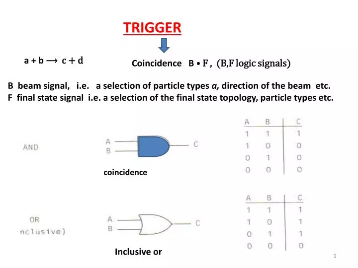
TRIGGER a + b ⟶ c + d Coincidence B ⦁ F , (B,F logic signals) B beam signal, i.e. a selection of particle types a, direction of the beam etc. F final state signal i.e. a selection of the final state topology, particle types etc. coincidence Inclusive or
Exclusive OR A B C 1 0 1 0 1 0 1 0 0 0 0 ⦁ Anticoincidence input coincidence input output
beam + target ⟶ a + b coincidence defines the beam profile anti (C) eliminates beam particles which do not interact ⦁ S,A,B,C scintillators Trigger signal: ⦁ A ⦁ B ⦁
Analog signal Digital signal ⦁ ⦁ ⦁ ADC Charge measurement Multichannel analyzer
Measuring of muon lifetime μ⟶ e + Muon stopped in lead absorber , then decays , electron is detected in B or C Lifetime is the time difference between muon signal and electron signal Muon : A ⦁B⦁ Electron: or
⦁ TDC ⦁ or TDC time-to-digital convertor
More realistic arrangement Muon is slowed down in the Pb absorbers Muon trajectory is selected by the counters Electron is detected in the counter Counter eliminates background muon: Electron:
BUSY (≡ INHIBIT) signal Digitization by an ADC, writing of this or other information need some time ⟹ it is necessary to block the system from any other event inhibit and busy method flip-flop ( ) If it is present, the gate is open and coincidence is working Output from the coincidence To flip flop ⟹ BUSY signal coincidence is closed To trigger Informations are read out ⟹ clear signal to the flip/flop ⟹ the coincidence is open, other event can be detected
Life time : the system is sensitive to the arriving events is present, which opens the gate , BUSY closes the gate the scaler counts, if the clear signal was send
Trigger F⦁ B , B - beam signal, F- final state signal 1) Beam signal, example target Scintillator counters, , with the suitable gas filling eliminates oter beam particles, p, π A anticoincidence veto , eliminates “halo” particles BC bem counters, used as a veto of events which detect a beam particle a proportional chamber which makes possible to detect one particle in the beam, i.e. one wire is hit only a proportional chamber which detects final state particles
2) Final state signal F, it is a combination of signal from various detectors which reflects event topologies Multiplicity of particles Directions of particle emissions Particle energies Type of particles etc. Example: the target is hydrogen, decay in the final state 2 charged particles Event topology: at some distance from the target ⟹ 2 tracks Final state: 0 particles just behind the target after some distance 2 particle Trigger: Neutron: no signal ⟹ around target no particle detected
Background: A layer of lead around the target Detector noise or
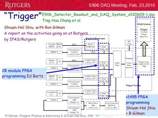
The trigger system must be complted by detectors for energy and momenta measurement (magnets, chambers, calorimeters etc..) and data acqusition system (DAQ)
Dead time non-extenable dead time, τ dead time when one event is pocessed τ detector is not sensitive to other events during τ The true number of counts k/T ≡ R is the experimental counting rate
2. Extendable case events extends dead time Distribution of time intervals t between events? ( for the detection t n number of detected events, The mean number of detected events in time period t is mt, m is the true rate
What is the distribution of time intervals t ? The normalized distribution is Distribution of number of events ≡ probabilty
Number of detected events ( or counts) in time T True number of events in time T To find the true value of rate m ⟹ a numerical solution
Measurement of the dead time k/T ≡ R the method of 2 sources the rate of both sources The rate of each source