Download

1 / 45
470 likes | 741 Views
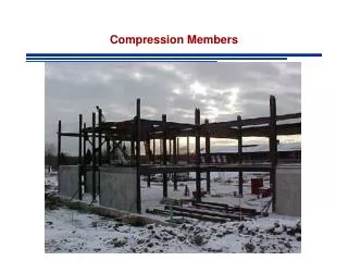
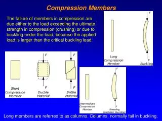
Compression Members. Compression Members. Compression members are susceptible to BUCKLING BUCKLING – Loss of stability Axial loads cause lateral deformations (bending-like deformations). P is applied slowly P increases Member becomes unstable - buckles. Column Theory.

E N D
Compression Members • Compression members are susceptible to BUCKLING • BUCKLING – Loss of stability • Axial loads cause lateral deformations (bending-like deformations) P is applied slowly P increases Member becomes unstable - buckles
Column Theory Axial force that causes Buckling is called Critical Load and is associated to the column strength • Pcr depends on • Length of member • Material Properties • Section Properties
Assumptions • Column is perfectly straight • The load is axial, with no eccentricity • The column is pinned at both ends No Moments Need to account for other boundary conditions
Other Boundary Conditions Free to rotate and translate Fixed on top Free to rotate Fixed on bottom Fixed on bottom Fixed on bottom
Other Boundary Conditions In general K: Effective Length Factor LRFD Commentary Table C-C2.2 p 16.1-240
AISC Requirements CHAPTER E pp 16.1-32 Nominal Compressive Strength AISC Eqtn E3-1
AISC Requirements LRFD
AISC Requirements ASD – Allowable Stress
Alternatively Inelastic Buckling
LOCAL BUCKLING • A.Flexural Buckling • Elastic Buckling • Inelastic Buckling • Yielding • B. Local Buckling – Section E7 pp 16.1-39 • and B4 pp 16.1-14 • C. Lateral Torsional Buckling
Local Stability - Section B4 pp 16.1-14 Local Stability: If elements of cross section are thin LOCAL buckling occurs The strength corresponding to any buckling mode cannot be developed
Local Stability - Section B4 pp 16.1-14 Local Stability: If elements of cross section are thin LOCAL buckling occurs The strength corresponding to any buckling mode cannot be developed
Local Stability - Section B4 pp 16.1-14 Local Stability: If elements of cross section are thin LOCAL buckling occurs The strength corresponding to any buckling mode cannot be developed
Local Stability - Section B4 pp 16.1-14 • Stiffened Elements of Cross-Section • Unstiffened Elements of Cross-Section
Local Stability - Section B4 pp 16.1-14 • Compact • Section Develops its full plastic stress before buckling (failure is due to yielding only) • Noncompact • Yield stress is reached in some but not all of its compression elements before buckling takes place (failure is due to partial buckling partial yielding) • Slender • Yield stress is never reached in any of the compression elements (failure is due to local buckling only)
Local Stability - Section B4 pp 16.1-14 If local buckling occurs cross section is not fully effective Avoid whenever possible Measure of susceptibility to local buckling Width-Thickness ratio of each cross sectional element: l If cross section has slender elements - l> lr Reduce Axial Strength (E7 pp 16.1-39)
Slenderness Parameter - Section B5 pp 16.1-12 Cross Sectional Element l Slenderness Stiffened Unstiffened b t h tw l=b/t=bf/2tw l=h/tw
Slenderness Parameter - Limiting Values AISC B5 Table B4.1 pp 16.1-16
Slenderness Parameter - Limiting Values AISC B5 Table B4.1 pp 16.1-17
Slenderness Parameter - Limiting Values AISC B5 Table B4.1 pp 16.1-18
Slender Cross Sectional Element:Strength Reduction E7 pp 16.1-39 Reduction Factor Q: Q: B4.1 – B4.2 pp 16.1-40 to 16.1-43
Slender Cross Sectional Element:Strength Reduction E7 pp 16.1-39 Reduction Factor Q: Q=QsQa Qs, Qa: B4.1 – B4.2 pp 16.1-40 to 16.1-43
Example I Investigate a W14x74, grade 50 in compression for local stability W14x74: bf-10.1 in, tf=0.785 in FLANGES - Unstiffened Elements Flange is not slender, OK
Example I Investigate a W14x74, grade 50 in compression for local stability W14x74: bf-10.1 in, tf=0.785 in WEB - Stiffened Element Web is not slender, OK
Example I Investigate a W14x74, grade 50 in compression for local stability W14x74: bf-10.1 in, tf=0.785 in PART 1 – Properties: Slender Shapes are marked with “c”
1.5 t = 0.1875 7.652 in 8 in Example II Determine the axial compressive strength of an HSS 8x4x1/8 with an effective length of 15 ft with respect to each principal axis. Use Fy=46 ksi. HSS 8x4x1/8 Ag=2.70 in2 h/t=66.0 rx=2.92 in2 b/t=31.5 ry=1.71 in2
HSS 8x4x1/8 Maximum OK Ag=2.70 in2 rx=2.92 in2 ry=1.71 in2 h/t=66.0 b/t=31.5 Example II Inelastic Buckling Nominal Strength
HSS 8x4x1/8 Ag=2.70 in2 rx=2.92 in2 ry=1.71 in2 h/t=66.0 b/t=31.5 Example II Local Buckling SLENDER
HSS 8x4x1/8 Ag=2.70 in2 rx=2.92 in2 ry=1.71 in2 h/t=66.0 b/t=31.5 Example II Local Buckling Stiffened Cross-Section – Rectangular w/ constant t Qs=1.0 AISC E7.2 Case (b) applies provided that Code allows f=Fy to avoid iterations Aeff: Summation of Effective Areas of Cross section based on reduced effective width be
be Example II Aeff:
Aeff: 1.5 t = 0.1875 be 7.652 in 8 in Example II Loss of Area
Example II Loss of Area Reduction Factor
Example II Local Buckling Strength Inelastic Buckling Same as before Nominal Strength
Example II Local Buckling Strength Nominal Strength CONTROLS Lateral Flexural Buckling Strength LRFD ASD
Column Design Tables Assumption : Strength Governed by Flexural Buckling Check Local Buckling Column Design Tables Design strength of selected shapes for effective length KL Table 4-1 to 4-2, (pp 4-10 to 4-316) Critical Stress for Slenderness KL/r table 4.22 pp (4-318 to 4-322)