Download
1 / 19
250 likes | 511 Views
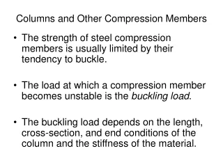
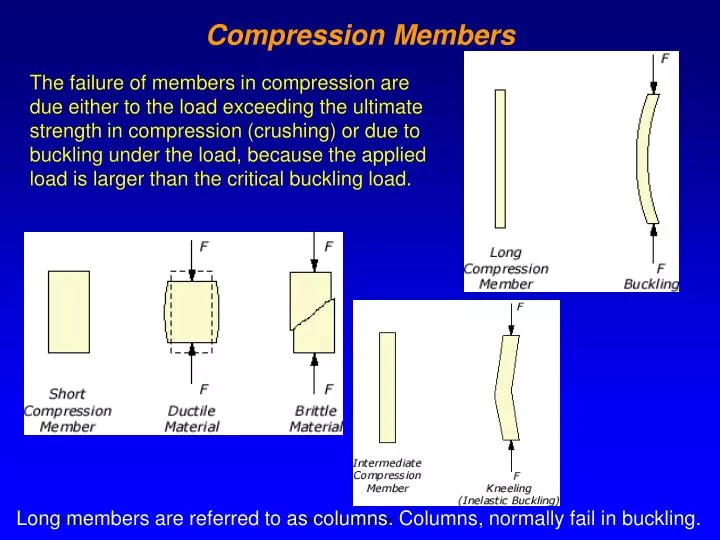
Compression Members. The failure of members in compression are due either to the load exceeding the ultimate strength in compression (crushing) or due to buckling under the load, because the applied load is larger than the critical buckling load.

E N D
Compression Members The failure of members in compression are due either to the load exceeding the ultimate strength in compression (crushing) or due to buckling under the load, because the applied load is larger than the critical buckling load. Long members are referred to as columns. Columns, normally fail in buckling. Mechanical Engineering Dept.
Compression Members Crushing failure – 1985 Mexico earthquake. Buckling failure Mechanical Engineering Dept.
Members in compression Connecting rods Compression Members Actuators Mechanical Engineering Dept.
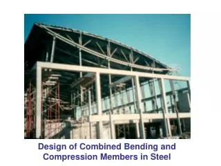
Compression Members Trusses Structures Mechanical Engineering Dept.
From deflection of beam, relating curvature to the moment, we have: d2y M = EI dx2 d2y P + = 0 y EI dx2 Rearranging the terms: P P y = A sin( x) + B cos( x) Second order, linear, and homogeneous differential equation EI EI Solution: Column Design – Euler Column Euler column – both ends are pinned or rounded Euler formula M = - Py Mechanical Engineering Dept.
Applying the first boundary condition: 0= (0) + B (1) B = 0 P P y = A sin( x) + B cos( x) Applying the second boundary condition: EI EI P 0 = A sin( l) For a nontrivial solution, A cannot be zero. Therefore: EI P P l = n , 0 = sin( l) Where n is an integer, n =1, 2, 3, …. EI EI Column Design – Euler Column y = 0 at x = 0 Boundary conditions y = 0 at x = l No deflections at the ends Mechanical Engineering Dept.
2E I Pcritical= Euler formula l2 Buckling is avoided if the applied load is less than the critical load Papplied<Pcritical Column Design – Euler Column The smallest load occurs when n = 1, therefore, P l = EI Note: the strength of a material has no influence on the critical load, only the modulus of elasticity effects the critical load Mechanical Engineering Dept.
Fixed-Free Fixed-pinned Fixed-Fixed 2E I Pcr= (leff)2 Euler Column – End Conditions and Effective Length Euler’s end condition Pinned-Pinned, or rounded-rounded Fixed-sliding American Institute of Steel Construction Mechanical Engineering Dept.
2E I Pcritical= Euler formula l2 Where Sr = (l/k) is called the slenderness ratio. 2E (Pcritical/A ) = (l/k)2 Design graph Sy 2E P / A Euler’s equation (l/k)2 l/kslenderness ratio Euler Column – Slenderness Ratio, Sr I = Ak 2 , where k = radius of gyration Failure by yielding Failure by buckling Safe zone Mechanical Engineering Dept.
Failure occurs in the safe zone Sy 2E 2E B Sy / 2 (l/k)2 (l/k)2 P / A (l / k)B l / kslenderness ratio Euler Column – Design Curve Sy Safe zone P / A l / kslenderness ratio Mechanical Engineering Dept.
2E 2E , (Sy / 2) = (Pcr/A ) = (l/k)B2 (l/k)2 2E (l/k)2 2K2E )1/2 K depends on the end condition (l/k)B= ( Sy Design Curve – Johnson’s Equation Point B is also on the Euler’s equation Sy B Sy / 2 P / A (l / k)B l / kslenderness ratio Mechanical Engineering Dept.
Johnson equation for short columns P / A = Sy at l / k = 0 2E (Pcritical/A)=a – b (l/k)2 Boundary conditions, P / A = Sy / 2 at l / k = (l / k)B (l/k)2 Design Curve – Johnson’s Equation Short column, Johnson eq. Long column, Euler eq. Sy B P / A Safe zone (l / k)B l / kslenderness ratio Mechanical Engineering Dept.
(Pcritical/A)=Sy – (Sy / 2)2 (1/KE) (l/k)2 2K2E )1/2 K depends on the end condition (l/k)B= ( Sy Design Curve – Johnson’s Equation Applying the boundary condition, (Pcritical/A)=a – b (l/k)2 a =Syand b = (Sy / 2) / (l / k)B Mechanical Engineering Dept.
d2y P – + = y EI dx2 Sy (Pcr / A ) = (eK / k2) Sec (l/k) (P / 4AE)1/2 1 + Pe EI The secant column formula Where (eK / k2) is called theeccentricity ratio Column Design – Eccentric Loading The Secant Formula M + Py + Pe = 0 Mechanical Engineering Dept.
Column Design Curve Mechanical Engineering Dept.
(Pcritical/A)=Sy – (Sy / 2)2 (1/KE) (l/k)2 Example – Column Design Design a column to carry a central load of 3600 lb. The column has to be 15” long. Due to space limitation the largest dimension cannot exceed 1.0 inch. The column will be welded at both ends. Select material → 1035 CD steel → E = 30x106 psi, and Sy = 67,000 psi Select cross section → tube with outside diameter not to exceed 1.0” Choose a safety factor → n = 4 Select thickness and calculate the outside diameter to obtain safety factor of 4. Johnson equation (Pcr/A)=67000 – (67000 / 2)2 (1/30x106) (l/k)2 (Pcr/A)=67000–3.79(l/k)2 Mechanical Engineering Dept.
Calculate the slenderness ratio for point B 2E (Pcr/A) = = (l/k)2 4 4 2 x 1 x 2x30x106 2 I =/64 (do – di ) 2 k = (I/A)1/2 = [ (do+ di ) / 16]1/2 )1/2 Area ( = 94 2 2 A =/4 (do – di ) 67000 Area moment of inertia 2K2E )1/2 Radius of gyration (l/k)B= ( Sy di =do – 2t Inside diameter Example – Column Design Euler equation 2.96x108 = (l/k)2 Mechanical Engineering Dept.
Use Euler eq. 1.0 0.625 0.479 0.295 50 < 94 27400 7.4 > 4 0.375 0.337 0.210 71 < 94 4.46 ≈ 4 16060 0.75 Use Johnson eq. Example – Column Design Select thickness t = 3/16 do di Pcr k l/k n = (Pcr / 3600) = 4 A 0.5 0.125 0.185 0.1288 116 > 94 4032 1.12 < 4 Specify, 1035 CD steel tube with outside diameter of 3/4” and thickness of 3/16” Mechanical Engineering Dept.
d = .713, select d = .75 2 d (.713)2 1.2 = = Weight ratio = (.75)2 – (.375)2 2 2 do– di Solid bar is 20% heavier Example – Column Design Consider a solid bar Johnson equation (Pcr/A)=67000–3.79(l/k)2 16060 15 =67000–3.79( )2 /4 (d) 2 d/4 Mechanical Engineering Dept.