Download
1 / 31
310 likes | 320 Views
Straw Tube Drift Chamber for the LHCb Tracking System. Beijing (Tsinghua University), 18-11-2002. Outline :. Detector Design and Test-beam Results: LHCb Tracking & OT Design OT Modules & Straw Tubes Gas Mixture & Drift Time. Electronics: FE Layout and TFC Distribution HV Boards

E N D
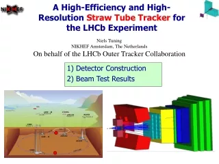
Straw Tube Drift Chamber for the LHCb Tracking System Beijing (Tsinghua University), 18-11-2002 Outline: Detector Design and Test-beam Results: LHCb Tracking & OT Design OT Modules & Straw Tubes Gas Mixture & Drift Time Electronics: • FE Layout and TFC Distribution • HV Boards • OTIS TDC Module Construction: • Straw Material • Injection Molding • Module Design & Prototypes • Station Frames
LHCb Tracking System B-production strongly “forward”-peaked LHCb ~ “forward” spectrometer • charged particles “analyzed” through magnet tracked with: • high-flux region (2%): Si detector (Inner Tracker) • remaining area (98%): straw drift-tubes (Outer Tracker) Antonio Pellegrino
Tracking System Functions • measure charged-particles momenta: • link VErtex LOcator CAL/msystem • provide angular info (with sufficient resolution) to Particle-IDentification system (RICH) Antonio Pellegrino
Tracking System Performance • high resolution: 10 MeV in “BS DS K” invariant mass dp/p ~ 0.4% • high efficiency(multi-particle f.s.): 80% rec. eff. “BS DS (KKp) K” 95% tracking efficiency Antonio Pellegrino
The Outer Tracker Design B-Field vertical measure x-coordinate OT Station consist of 4 layers: XUVX (qU,V = 5o sufficient to reduce combinatory) modular design: layers are composed of modules Antonio Pellegrino
The Outer Tracker Design (cont’d) IT/OT Boundary optimized on the basis of occupancy studies: require average occupancy < 10% Occupancy (%) position along z (a.u.) Antonio Pellegrino
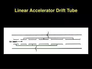
OT Module Design Straw Tubes packed in double-layered modules • 64-cells wide • only ~0.7% of 1 X0: • “light” panels (honeycomb core with carbon skins) • “light” straws Antonio Pellegrino
Straw Tubes Cell diameter ~5mm: • reasonable occupancy • sufficiently fast signal collection time • T 25ns , unrealistic • T 50ns , workable (Contamination of events from neighboring bunch crossings) Antonio Pellegrino
Gas Mixture and Drift Time T 50ns fast drift gas: add CF4 to basic Ar/CO2 mixture Drift-time spectra measured … Ar(65)/CO2 (5)/CF4 (30) Drift time (ns) …and reproduced with GARFIELD simulation Antonio Pellegrino
Test Beam Results Measured t-r relation, coordinate resolution (~0.2mm), efficiency (~96%), etc. Drift time (ns) Distance from Wire (mm) Ar(75)/CO2 (10)/CF4 (15) selected as baseline Antonio Pellegrino
Straw Material CF4 presence chose polymer as straw material: • 0.040 mm thick Kapton XC (25% volume doping with Carbon), (370 W/cm2 ~12 KW/m) • Passed extensive ageing tests • two windings ensure sufficient gas tightness Antonio Pellegrino
Straw Cross Talk The cathode (straw) material determines the level of analog (straw-to-straw) cross-talk I.e. different choices of the outer winding material: • 0.025mm Aluminum 0.5% analog cross talk • 0.040mm Kapton XC 1.8% analog cross talk Baseline solution: outer winding of pre-laminated Kapton XC (0.025mm)/Aluminium(0.012mm) foil (Straw winding material budget ~0.12 of 1X0) Antonio Pellegrino
Injection-Molded Parts For the construction of the OTR modules a large number (~400000) of “small” pieces is required: • wire locators: inserted in the straw to support the wire every 80 cm • middle- and end-blocks: support wire at straw ends and define counting-gas volume This large number of small parts can be produced with injection-molding techniques, without compromising the tight local tolerances (0.020.05mm) Antonio Pellegrino
Detailed Design of Detector Modules Antonio Pellegrino
Module Prototypes OT Module Prototype (2.5m long) built at NIKHEF Antonio Pellegrino
Module Prototypes (cont’d) OT Module Prototype (1m long) built at Heidelberg Antonio Pellegrino
OT Electronics FE Electronics: wire feed-through, HV, preamp, TDC On-Detector FE Electronics: Data serializer FE Electronics: Control & Bias, Monitor,… L1 Electronics Counting Room DAQ and L1 Farm Antonio Pellegrino
OT Electronics (cont’d) Antonio Pellegrino
FE Electronics GOL OTIS OTIS ASDBLR ASDBLR ASDBLR ASDBLR HV board Antonio Pellegrino
FE Electronics Components Antonio Pellegrino
FE Electronics Assembly Antonio Pellegrino
FE Electronics Mock-up Models Needs modeling to assess mechanical details GND Spring +HV SMD connector Antonio Pellegrino
HV Boards Not just a bunch of capacitors! Strict demands: • signal (2fC/10ns 300W = 0.06 mV) and HV (~1500V) separation • good transmission of fast (~10ns) signal GND plane all along signal path • noise level << signal (2fC/10ns = 200 nA) • compact design: 5mm channel pitch and small-space constraints (~40mm for the whole thickness of the FE box) • high reliability: 10 years operation with scarce possibilities of access for repair Antonio Pellegrino
HV Boards Design Main design ingredients: • high-quality capacitors JOHANSON 302R29W331KV4E • capacitors “buried” inside the PCB First prototypes unsuccessful: after 4 weeks test, 19 broken channels out of 10x32 (6 out of 10 boards with at least one broken channel)! • air gap under capacitors • remains of cleaning “slurry” • inaccurate hand-placing of capacitors Antonio Pellegrino
HV Boards Production Improved production procedure (19 HV boards): • carried out under vacuum • pick-and-place glueing avoids air-gap under capacitors • accurate (robot) placement of capacitors • soldering area cleaned with plasma (instead of slurry) First tests: ITOT(608chans) < 50nA, up to HV=+2.5kV and T=80oC Long-term tests of ~1000 channels forthcoming… Antonio Pellegrino
OTIS TDC 4 x 320MBit/s • Drift time measurement • Mounting on detector • Approx. 50,000 channels • 4 TDC (32 channels each) gets serialised and transmitted optically (1.28GBit/s) 9.6GBit/s • OTIS TDC designed at ASIC Heidelberg (Harald Deppe, Uwe Stange, Ulrich Trunk, Ulrich Uwer) • Chip Requirements: 1ns resolution (6 bit) drift times of up to 50ns 40MHz, clock driven design 1.1MHz L0 trigger rate up to 10% occupancy 4µs trigger latency radiation hard design (pipeline length: 160) Antonio Pellegrino
OTIS v1.0 • First prototype with basic functionality • ~700.000 transistors • 5100µm x 6000µm • Tape out: 15/04/2002 • Delivery: 29/07/2002 • Small test PCB with possibility to connect ASD and GOL chips Antonio Pellegrino
OTIS v1.0 (cont’d) OUTLOOK • Further investigations concerning drift time encoding • More chips, performance tests, random trigger tests, ... • Operation with detector prototype • Commissioning of the read out chain including TTCrx Antonio Pellegrino
Station Frames Proposal contained in the OT TDR… modules mounted with dowel pins onto Al precision strips defining the module positions 4 layers of each station mounted on Al frames each frame consists of two halves …a mock-up module for study was also built at NIKHEF Antonio Pellegrino
Station Frames (cont’d) Working group to revise frame-design constraints and solutions: • Collaborate with ITR group for common solution • Revise global strategy: • Stations should move independently • Positioning accuracies and reproducibility • Krakow group producing a case study Global Movement (TDR) Independent Movements (Krakow) Antonio Pellegrino
Project Milestones Antonio Pellegrino