Download
1 / 36
380 likes | 633 Views
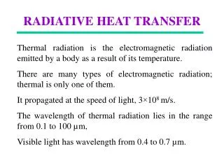
Radiative Heat Trade-Offs for Spacecraft Thermal Protection. A Practical Guide to Thermal Blanket/Multi-Layer Insulation Design. Scott Franke AFRL/VSSV. Thermal Radiation Trade-offs Overview. Thermal Radiation Basics

E N D
Radiative Heat Trade-Offs for Spacecraft Thermal Protection A Practical Guide to Thermal Blanket/Multi-Layer Insulation Design Scott Franke AFRL/VSSV
Thermal Radiation Trade-offs Overview • Thermal Radiation Basics • Properties and Relations: View Factor, absorptivity, emissivity, Stefan-Boltzmann, thin-plate ODE • Radiation Geometries: Parallel Plates, Convex Object in Large Cavity • Sources: Solar Radiation, Earth Radiation, Albedo • Materials • Radiative Comparison • Long Term Exposure Degradation • Multi-Layer Insulation (Thermal Blanket / Shroud) • Orbit Considerations • GEO, LEO, Lagrange points, Inclination • Design Examples • Design for Stabilization of Oscillating Heat Flux • @ LEO • Oscillation due to orbit: sun/shadow (umbra) • Design for Specific Temperature with Constant Heat Flux • @ Sun-Earth Lagrange (L2) point: • Stationary position relative to Earth. • Summary/Questions
Thermal Radiation Basics: Properties and Relations Surface finish dependent; want low values for both • No medium required, only “optical” transmission • Only effective heat transfer method in “empty” space • unless very low earth orbit (drag convection conduction) • Properties for transmission: • Absorptivity, α: ability for the surface to absorb radiation. • Emissivity, ε: ability for the surface to emit radiation. • View factor, F12: relates fraction of thermal power leaving object 1 and reaching object 2. • Used when a sink can see more than one source • Relations: • Blackbody vs. Greybody radiation • Blackbody is ideal emitter (max case): ε ≡ 1 • Greybody is anything less than blackbody, 0 < ε < 1 • Stefan-Boltzmann relation (any greybody): Note: q is really area-normalized q-dot (W/m2) σ = Stefan-Boltzmann Constant
Thermal Radiation Basics: Properties and Relations • Simple time ODE for radiantly heated thin plate: • In order to use such a simple equation: Assumptions. • 1) Our thermal blanket/MLI behaves as a “thin plate” • 2) Density is uniform • 3) Temperature is same everywhere on blanket (big assumption) • Why bother then? • Because it gives us a good rough approximation without using a FEM model • Hard to model with FEM thermal blanket irregular/unpredictable geometry • “Reliably vague” (ballpark reliability) ρ = material density σ = Stefan-Boltzmann h = material thickness c = material heat capacitance
Thermal Radiation Basics: Radiation Geometries 1 2 1 F12 = 1 2 Heat flux (W/m2) between: Two large (infinite) plates Small Convex Object in a Large Cavity F12 = 1 (View Factor)
Thermal Radiation Basics: SourcesFlux (W/m2) • Solar Radiation • Sun radiates at blackbody temperature of ~5000K Solar Constant: ~1350 W/m2 • q = 1350 ·α · cos(Ψ) • Ψ is angle between S/C normal to the sun • Largest heat source by far • Function of S/C attitude only • Earth Blackbody Radiation • View factor specific (how close you are to earth compared to sun) • T (Earth blackbody) = 289 K • q = σ · T4 · α · F • Function of S/C attitude AND orbit • Earth Albedo • Reflected light from sun • q = 1350 · AF · α · F · cos(θ) • Function of S/C attitude, orbit, AND season/latitude/longitude AF = Albedo Factor ~ 0.36 on average AF is a measure of reflectivity of Earth’s surface. θ = Angle between S/C surface and sun (θ is 90 degrees out of phase with Ψ)
Thermal Radiation Trade-offs Overview • Thermal Radiation Basics • Properties and Relations: View Factor, absorptivity, emissivity, Stefan-Boltzmann, thin-plate ODE • Radiation Geometries: Parallel Plates, Convex Object in Large Cavity • Sources: Solar Radiation, Earth Radiation, Albedo • Materials • Radiative Comparison • Long Term Exposure Degradation • Multi-Layer Insulation (Thermal Blanket / Shroud) • Orbit Considerations • GEO, LEO, Lagrange points, Inclination • Design Examples • Design for Stabilization of Oscillating Heat Flux • @ LEO • Oscillation due to orbit: sun/shadow (umbra) • Design for Specific Temperature with Constant Heat Flux • @ Sun-Earth Lagrange (L2) point: • Stationary position relative to Earth. • Summary/Questions
Materials: Radiative Property Comparison Material absorptivity (α) varies with temperature of source. Anodized Aluminum (13) Polished Aluminum (15)
Materials: Radiative Property Comparison • Not easily found via web • www.matweb.com some data on certain materials, emissivity is searchable
Materials: Degradation 10 yrs @ Simulated GEO (also, LDEF) • Cosmic Rays, Solar Storms, etc. deteriorate paint over time. • Thin films used in for Multi-Layer Insulation (MLI) can also degrade over long term: Tedlar thin film exposed To 3 yrs simulated GEO
Materials:Multi-Layer Insulation (MLI) / Thermal Blanket Heat leaking through layers. Ф = maximum heat flux encountered Dacron filling n layers • Typically Aluminized Mylar • Hubble ST: Aluminized Teflon FEP • (fluorinated ethylene propylene) • “Dacron” Polyethylene Terephthalate (PET) deposited between each sheet • Layers expand like a balloon due to lack of • pressure on orbit negates conductivity • Protects against orbital debris / micrometeoroids
Thermal Radiation Trade-offs Overview • Thermal Radiation Basics • Properties and Relations: View Factor, absorptivity, emissivity, Stefan-Boltzmann, thin-plate ODE • Radiation Geometries: Parallel Plates, Convex Object in Large Cavity • Sources: Solar Radiation, Earth Radiation, Albedo • Materials • Radiative Comparison • Long Term Exposure Degradation • Multi-Layer Insulation (Thermal Blanket / Shroud) • Orbit Considerations • GEO, LEO, Lagrange points, Inclination • Design Examples • Design for Stabilization of Oscillating Heat Flux • @ LEO • Oscillation due to orbit: sun/shadow (umbra) • Design for Specific Temperature with Constant Heat Flux • @ Sun-Earth Lagrange (L2) point: • Stationary position relative to Earth. • Summary/Questions
Orbit Geometry Considerations (GEO)Simple Case: Zero Degree Inclination (2D Planar Orbit) Sunlight Earth Radius: RE = 6.378 x10³ km Altitude (GEO) = 35.785 x10³ km Rorbit = RE + GEO = 42.163 x10³ km 4.8% of the 2D GEO orbit sweeps through the Umbra Umbra boundary Umbra boundary Earth Surface Orbit “Top-down” (North facing South) view of Earth
Orbit Geometry Considerations (LEO)Simple Case: Zero Degree Inclination (2D Planar Orbit) Sunlight Earth Radius: RE = 6.378 x10³ km Altitude = 150 n.mi. = 0.278 x10³ km Rorbit = RE + Altitude = 6.656 x10³ km Earth Surface Orbit Umbra boundary 40% of the equatorial orbit sweeps through the Umbra (Order of magnitude higher than GEO!!) Umbra boundary “Top-down” (North facing South) view of Earth
LEO Inclination Concerns (more significant than GEO) The 2D-planar orbit is a rough approximation of the sunlight geometry. Seasons (axis tilt) and inclination will change the percent of orbit that sweeps through the umbra. 0% of orbit sweeps through Umbra (constant sunlight on one side) Orbit sweeping through Umbra << 40% Umbra Sunlight 60o Inclined Orbit 90o Polar Orbit An extreme case: 60o Inclination dT/dt lower than equatorial case The Most Benign Case Possible dT/dt = 0 From these cases, one can see that the zero degree case (at solstice) for LEO has the highest dT/dt possible, and represents the worst thermal transient condition.
Thermal Radiation Trade-offs Overview • Thermal Radiation Basics • Properties and Relations: View Factor, absorptivity, emissivity, Stefan-Boltzmann, thin-plate ODE • Radiation Geometries: Parallel Plates, Convex Object in Large Cavity • Sources: Solar Radiation, Earth Radiation, Albedo • Materials • Radiative Comparison • Long Term Exposure Degradation • Multi-Layer Insulation (Thermal Blanket / Shroud) • Orbit Considerations • GEO, LEO, Lagrange points, Inclination • Design Examples • Design for Stabilization of Oscillating Heat Flux • @ LEO • Oscillation due to orbit: sun/shadow (umbra) • Design for Specific Temperature with Constant Heat Flux • @ Sun-Earth Lagrange (L2) point: • Stationary position relative to Earth. • Summary/Questions
Design for Stabilization of Oscillating Heat Flux(Typical for LEO orbit) • Given • 90 minute orbit, LEO altitude, 0 degree inclination • Orbit is around earth, satellite sweeps through earth’s shadow (Umbra) periodically. • Consider Solar, Earth, and Albedo radiation flux. • Satellite is always pointed at Nadir (angular rotation rate is orbit rate) • Temperature fluctuates due to Umbra sweep but eventually achieves an average steady state. (nominal temperature, To) • Find • Thermal blanket MLI material specification and number of layers to keep satellite structural members at nominal delta T < ± 0.5 K to prevent large thermal expansion in members. • Strategy • Model MLI blanket as a thin plate • Use simple ODE
Multi Layer Insulation (MLI) Design Overview A B A qAB= f (ΔT) A qleak qAB Required: B Assumption: Shroud modeled as thin circular plate. Heat leaking through MLI can not be more than heat between surfaces A and B, limited by design requirement: ΔT = 1 K. External Heat flux (Ф) Sun + Albedo + Earth MLI Spacecraft structural members modeled as small convex object in a large cavity. Heat qAB is omnidirectional throughout shroud (assumption).
LEO Geometric Considerations (revisited)Simple Case: Zero Degree Inclination (2D-Planar Orbit) Sunlight Earth Radius: RE = 6.378 x10³ km Altitude = 150 n.mi. = 0.278 x10³ km Rorbit = RE + Altitude = 6.656 x10³ km Earth Surface Orbit Umbra boundary 40% of the equatorial orbit sweeps through the Umbra Umbra boundary “Top-down” (North facing South) view of Earth
Thermal Radiation Flux Profile for One Equatorial OrbitBased on view factor andsatellite-earth angle Umbra Region: (~40% of orbit)
Thermal Radiation Flux Profile Explained:Change Due to Orbit/Sun Angle Umbra Region: (~40% of orbit) 2D plate model
Temperature Response Showing Steady State(Time ODE calculation for Thin Plate) To ~ 340 K
Multi-Layer Insulation Design Computation (Droopy Eyes!) Shroud, A B TO = 340 K From previous, nominal temperature for 2D orbit: Worst case for objects inside emissivity = 1: MLI (material dependent) emissivity: Stefan-Boltzman Constant: From design requirement: Unit heat flow between two surfaces of emissivity: (Small convex object in a large cavity depends only on small object’s emissivity) Linearizing the above: (see NASA contractor report 3800) Solving for surface to surface heat flux: (± 0.5 K)
MLI Design Computation Concluded qAB= f (ΔT) A Required: qleak qAB B From before, surface-surface heat flux: (known) Worst case thermal radiation from external sources: (known) heat leaking through MLI: (unknown due to n) To find n, relate qleak <= qAB: (solve for n) Ф = f (outer material, geometry) ε leak = MLI material dependent ε B = always 1 (worst case)
MLI Design Tradeoffs (LEO, equatorial) INPUT OUTPUT
Design for Constant Heat Flux • Given • Spacecraft at Sun-Earth Lagrange L2 point • No orbit about Earth, only about the sun. No shadow sweeps. • Consider Solar heat flux only, since View Factor for Earth is negligible. • Maneuver time is about four hours, (angular rotation rate is very slow) • Temperature is constant once at desired rotated position • Find • Thermal blanket MLI material specification and number of layers to keep satellite structural members at nominal temperature of 200K. • Strategy • Model MLI blanket as a thin plate • Use simple ODE to achieve settling time within 4 hours and discover steady state temperature • Specify number of layers, material specs to get steady state temp. to 200K
z x y L2 lies 1.5 million km from Earth, 1% farther from the sun than the earth 300,000 km Lissajous Orbit Avoids a ~13,000 km-radius Earth shadow Constant Radiation: Large Lissajous orbit about S-E L2 Conclusion: Thermal Environment is stable. Source: http://astro.estec.esa.nl/GAIA/Assets/Papers/IN_L2_orbit.pdf
Thermally Stable Orbit (Worst Case for Steady State Temperature) Assumption: gold foil material exterior Solar, Albedo and Earth Fluxes calculated to be: Total Constant Heat Flux : Using ODE for Radiantly Heated Thin Plate: Steady State Temp = 583.7 K (exterior) Note: Gold Melting Point = 1337 K Temp. Settling Time = 3–5 hours (~580 K) Note: Maneuver Time = 4 hours max
Two Methods for Modeling Shroud and Contents Shroud, A qAB ΔT B qleak qleak Text To Text Method 1 (previous): Using the method the same as for the fluctuating heat: Equation above is Transformed into: Also: So, design parameter is: This only holds if temperatures are close to the desired nominal temperature (200 K). See Hedgepeth, pg. 9. (NASA contractor report 3800) However, as we have seen from the steady state computation: Text = 580 K >> 200 K !!!! This method may not hold.
Two Methods For Modeling Shroud and Contents Method 2 ( A better approximation?) : Model as 2D planar surface (contents surfaces) enclosed by another 2D plate (shroud surface) Equation for heat leaking across two parallel plates with N shield layers: Where q12 is the heat flux between plates with no shielding: Shroud, A qAB B ΔT qleak qleak Text Text To Outside plate: Shroud exterior, Text N shield layers (A) Inside plate (B), To ε1 ε2 T1 = To and T2 = Text
MLI Design Method 2 Similar to method 1 except solve for N with definite T2 and T1 known: Solving these four equations gives: ΔT = 1 K (Proposed sub-requirement) To = 200 K (Given requirement) T1 = 200 K T2 = 580 K (Steady state exterior temperature) ε1 = 1 (Worst case for telescope/truss surfaces) ε2 = 0.03 (Gold emissivity) Note: T2 and ε2 depend on material selected. T2 also depends on external heat flux (Ф) from Sun and Earth, etc.
Differences between Method 1 and Method 2 Method 2: Two Parallel Plates Method 1: Small Convex Object Enclosed in Large Cavity External Temperature n = f (Heat Flux, Material) N = f (External Temperature, Material) f (Heat Flux)
Thermal Shroud Design Results *Valid = steady state temperature close to nominal **Questionable if silver can be used as coating Conclusion: 5 Ag layers, 107 Au layers, 24 Al layers
Thermal Radiation Trade-offs: Summary / Questions • Space Thermal Environment Dependencies: • Orbit Altitude (GEO, LEO, L points) • Inclination • S/C Attitude • Design Issues • Materials • Modeling (geometry, assumptions) • Given requirements or desirements (delta T, etc.) • Analytical Insight (ODE, FEM)
Thermal Radiation Trade-offs 4. http://www.swales.com/products/therm_blank.html 5. http://setas-www.larc.nasa.gov/LDEF/index.html 6. http://www.aero.org/publications/crosslink/summer2003/07.html