Download
1 / 44
440 likes | 444 Views
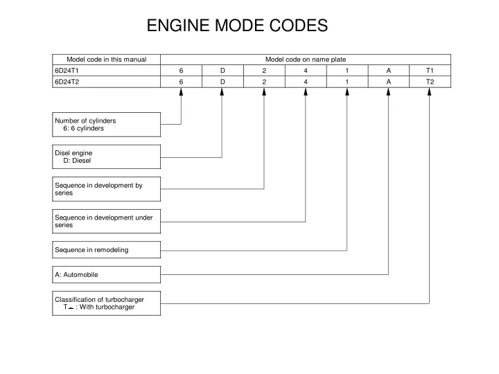
ENGINE MODE CODES. Engine Number. Engine number is punchmarked on the position as illustrated. Name plate shows vehicle model, chassis number, and engine model. 1 Vehicle model 2 Chassis number 3 Engine model. Engine Name Plate.

E N D
Engine Number Engine number is punchmarked on the position as illustrated. • Name plate shows vehicle model, chassis number, and • engine model. • 1 Vehicle model • 2 Chassis number • 3 Engine model
Engine Name Plate The engine name plate is attached to the position shown in the illustration. • The following items are indicated. • 1 Engine model • 2 Valve clearance • 3 Firing order • 4 Fuel injection timing
1 Rocker • 2 Valve cap • 3 Valve cotter • 4 Upper retainer • 5 Outer valve spring • 6 Inner valve spring • 7 Lower retainer • 8 Valve • 9 Camshaft • 10 Tappet • 11 Push rod • 12 Valve guide • 13 Valve stem seal • 14 Rocker shaft bracket • 15 Lock nut • 16 Adjusting screw • 17 Rocker cover • The valve stem seal 13 is fitted onto the valve 8 to control he amount of lubricant flowing onto the sliding surfaces of the valve and valve guide 12. • The valve springs 5, 6 are unevenly pitched to prevent abnormal vibration at high speeds. To prevent the inner and outer springs from meshing with each other, the springs are wound in opposite directions. • To facilitate removal and reinstallation of the camshaft 9 from the rear end of the crankcase, the diameter of each camshaft bearing is smaller toward the front of the engine.
PISTONS AND CYLINDER LINERS SIZES PİSTON SIZE MARK A B C CYLINDER LINER MARK A B C A, B, C arası fark 0,012mm dir. D Over Size: 0,5, 0,75, 1.00 mm
CONNECTING RODS 1 Connecting rod bushing 2 Connecting rod 3 Upper connecting rod bearing 4 Connecting rod bolt 5 Lower connecting rod bearing 6 Connecting rod cap a : Weight mark stamp “A” to “H”, “J” to “M” (where “A” indicates the greatest connecting rod weight) b : Alignment mark c : Lug
PISTONS • a : Part number • b : Weight mark • c : Size mark • Standard pistons are marked “A”, “B” or “C” • (where “C” indicates the greatest outside diameter). • d : Cooling cavity • e : Front mark“F” and “¬” • The pistons selected must bear the same size • marks as the cylinder liners.
ROCKER COVER, CYLINDER HEAD AND VALVE MECHANISM • Disassembly sequence • 1 Bolt • 2 Injection nozzle • 3 Oring • 4 Nozzle tip gasket • 5 Bolt • 6 Bushing • 7 Insulator • 8 Rocker cover gasket • 9 Rocker cover • 10 Bolt • 11 Rocker and bracket assembly 12 Oring • 13 Cylinder head bolt (short) • 14 Cylinder head bolt (long) • 15 Cylinder head and valve assembly 16 Cylinder head gasket • 17 Push rod • 18 Side cover • 19 Tappet • A: Locating pin • X: Nonreusable part
CYLINDER HEAD AND VALVE ASSEMBLY • Cylinder head and valve assembly • [Removal] • Before loosening the cylinder head bolts 13, 14, make sure all the valve springs are free by loosening the adjusting screw C on rocker A in case this is compressing its valve spring B due to the action of its push rod 17.
LOOSEN AND REMOVE THE CYLINDER HEAD BOLTS • Loosen and remove the cylinder head bolts 13, 14 in the sequence shown. Each • cylinder head bolt should be loosened a little at a time.
TIGHTEN THE CYLINDER HEAD BOLTS • Before fitting any cylinder head bolt 13, 14, check the punch marks D on its head. Do not use the bolt if there are more than two punch marks. • The punch marks indicate the number of times each bolt has • been tightened using the plastic area tightening method. Any • bolt that already has three punch marks must be replaced. • Tighten the cylinder head bolts 13, 14 to the specified torque (180 N·m {18 kgf·m}) in the sequence shown and then confirm that the bolts 1, 2 and 3 are correctly tightened to 180 N·m {18 kgf·m}. (If the torque is insufficient, tighten them additionally.) After that, turn the bolts further in accordance with the following procedure. • G : Socket • H : Rod • J : Rod (extension)
ROCKER AND BRACKET ASSEMBLY • Disassembly sequence • 1 Thrust plate • 2 Rocker assembly <Inlet> • 3 Rocker assembly <Exhaust> • 4 Lock nut • 5 Adjusting screw • 6 Rocker bushing • 7 Rocker • 8 Rocker shaft bracket • Assembly sequence • Follow the disassembly sequence • in reverse.
SERVICE PROCEDURE • Rocker bushing • [Removal] • J: Rocker Bushing Puller • [Installation] • Set the components as illustrated such that the oil hole A in the rocker bushing 6 is aligned with the oil hole B in the rocker 7. • C : Seam of bushing • D : Chamfered side of rocker • Using the J Rocker Bushing Puller, • install the rocker bushing 6 into the • rocker 7 until the puller touches the • chamfered side D of the rocker.
VALVE GUIDES REMOVAL AND INSTALLATION 30091-08100 Exhaust : 0.09 - 0.12 mm Limit: 0.2 mm Inlet : 0.05 - 0.09 mm Limit: 0.2 mm If any clearance exceeds the specified limit, replace the defective part(s).
ADJUSTMENT VALVE CLEARANCES • NOTE • When taking measurements using the J Feeler Gauge, the gauge should be • able to move in the clearance with some resistance. Accurate measurements • can not be taken if the gauge moves loosely in the clearance.
TIGHTENING TORQUE 1- TORK DEĞERLERİ 180 Nm veya 18Kgfm (Islak) 2- AÇI DEĞERİ 90 YENİDEN SIKMA 1000 Km-Yeni araç =>10º 4000 Km-Bakımdan Sonra =>10º
Removal sequence • 1 Nut • 2 Lower connecting rod bearing • 3 Connecting rod cap • 4 Upper connecting rod bearing • 5 Piston and connecting rod assembly6 Oring • 7 Oring • 8 Rubber packing • 9 Cylinder liner • *a: Oil pan L Gr12 • *b: Crankcase L P1156 • X: Nonreusable part • Installation sequence • Follow the removal sequence in reverse.
PISTON PROJECTION • Service procedure • Predisassembly inspection • (1)Piston projection from crankcase top surface • NOTE • The piston projections affect engine performance • and must therefore be checked. • Measure the projection of each piston at four points • and calculate the average of the four values. • A : Front of engine • If the average value is out of specification, check the clearances between all relevant parts.
Predisassembly inspection • Crankshaft end play • Before removing the main bearing caps, measure the extent of crankshaft end play. • If the measurement exceeds the specified • limit, replace the thrust plates with • oversize ones.
MAIN BEARING CAPS 11-60
CRANKSHAFT MAIN BEARINGS [Installation] Install the main bearings 7, 16 such that their lugs A fit into the corresponding grooves. The upper main bearing 16 has an oil hole B. The lower main bearing 7 has no oil hole. Take care not to confuse the upper and lower parts.
CAMSHAFT BUSHINGS Disassembly sequence 6, 5, 4, 3, 2, 1, 7 Assembly sequence 5,4,3, 2,1 6 7