Download
1 / 26
260 likes | 271 Views
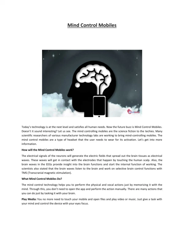
Mind Control of Systems. Designing a system to measure brain waves in order to obtain commands to control the direction of a remote-control car By Gary Obenski & Jim Bradbury. Primary Goals. Determine an efficient way to obtain brain wave signals from human subject

E N D
Mind Control of Systems Designing a system to measure brain waves in order to obtain commands to control the direction of a remote-control car By Gary Obenski & Jim Bradbury
Primary Goals • Determine an efficient way to obtain brain wave signals from human subject • Determine a way to change different wave patterns to commands such as ‘left’ and ‘right’
Electroencephalography • Science of recoding electric currents produced by human brain • Discovered by Hans Berger in late 1920’s
Brain waves • Arise from cerebral cortex • Byproduct of normal brain function • Millions of pyramidal cells produce small currents as the nerve impulses change
Four types of waves Alpha Beta Delta Theta
Similar experiments • Mind control by rats • US Air Force flight simulator
Biofeedback • Alternative method to try to interpret brain wave signals • Trains individual to learn how to produce specific frequencies
Where to go now… • Acquire the means to harness EEG waves (Integration of Amplifier and Filter) • Interpret signal as “1’s” and “0’s” • Condition subject to consistently produce desired signal • Interface EEG waveform to computer software • Change the world!!!
Initial Design • Differential amplifier • Minimum gain of 10,000 • Bandwidth of 0.5 Hz to 50 Hz • Low noise
Options • Buy amplifier • Easier • Cost consideration • Design amplifier • More difficult • More flexible
Amplifiers • Brainmaster circuit • Modified instrumentation amplifier
Brainmaster circuit specs • Gain : 20,000 • Bandwidth : 1.7 – 34 Hz • Input Impedance : 10 Mohms • CMRR : 100 dB
Instrumentation amp frequency response • Gain : 20,000 • Bandwidth : 0.2 Hz - high value (depends on gain-bandwidth product of op-amp)
Test • Compare each circuit • Modify if needed • Decide which one to use • Flexibility • Cost • Performance
Specs • Gain : 20,000 V/V 86 dB • Bandwidth : 1.25 - > 1 kHz • CMRR : 102 dB
Problems with BrainMasterand Solution • Voltage Divider of 10000 would not register any AC Signal • Unable to Couple the Two Stages SOLUTION: Always have an alternative design it case one goes wrong.