Download
1 / 37
370 likes | 372 Views
Explore the difficulties of system design and learn strategies to simplify the process. Understand the importance of design goals, system decomposition, and trade-offs. Discover how nonfunctional requirements can suggest design patterns.

E N D
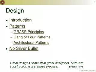
Design “There are 2 ways of constructing a software design: One way is to make it so simple that there are obviously no deficiencies, and the other way is to make it so complicated that there are no obvious deficiencies.” - C.A.R. Hoare
Why is Design so Difficult? • Analysis: Focuses on the application domain • Design: Focuses on the implementation domain • Design knowledge is a moving target • A design decision’s rationale changes rapidly • Half-life of knowledge in software engineering: About 3-4 years • What’s done today is out of date in 3 years • Cost of hardware rapidly sinking • Design window: Time frame for making design decisions.
The Purpose of System Design Problem • Bridge the gap between desired & existing system. • Use Divide & Conquer • Model the new system as a set of subsystems. New System Existing System
1. Design Goals Defi nition T rade-of fs 8. Boundary Conditions Initialization T ermination System Design System Design Failure 2. System Decomposition Layers/Partitions Coherence/Coupling 7. Software Control Monolithic Event-Driven Threads Conc. Processes 3. Concurrency 6. Global 4. Hardware/ Identification of Threads 5. Data Resource Handling Softwar e Management Mapping Access control Security Persistent Objects Special purpose Files Buy or Build Trade-off Databases Allocation Data structure Connectivity
Use the Requirements Analysis for System Design • Nonfunctional requirements => • Activity 1: Design Goals Definition • Use Case model => • Activity 2: System decomposition • Define subsystems based on functional requirements, coherence, & coupling. • Object model => • Activity 4: Hardware/software mapping • Activity 5: Persistent data management • Dynamic model => • Activity 3: Concurrency • Activity 6: Global resource handling • Activity 7: Software control • Activity 8: Boundary conditions
Section 1. Design Goals • Good documentation • Well-defined interfaces • User-friendliness • Reuse of components • Rapid development • Minimum # of errors • Readability • Ease of learning • Ease of remembering • Ease of use • Increased productivity • Low-cost • Flexibility • Reliability • Modifiability • Understandability • Adaptability • Reusability • Efficiency • Portability • Traceability • Fault tolerance • Backward-compatibility • Cost-effectiveness • Robustness • High-performance
Developer/ Maintainer Relationship Between Design Goals End User Functionality User-friendliness Ease of Use Ease of learning Fault tolerant Robustness Low cost Increased Productivity Backward-Compatibility Traceability of requirements Rapid development Flexibility Runtime Efficiency Reliability Portability Good Documentation Client (Customer, Sponsor) Minimum # of errors Modifiability, Readability Reusability, Adaptability Well-defined interfaces
Typical Design Goal Trade-offs • Functionality vs. Usability • Cost vs. Robustness • Efficiency vs. Portability • Rapid development vs. Functionality • Cost vs. Reusability • Backward Compatibility vs. Readability
Nonfunctional Requirements Suggest Design Patterns • The problem statement identifies potential design patterns • Text: “manufacturer independent”, “device independent”, “must support a family of products” • Abstract Factory Pattern • Text: “must interface with an existing object” • Adapter Pattern • Text: “must deal with the interface to several systems, some of them to be developed in the future”, “ an early prototype must be demonstrated” • Bridge Pattern
Nonfunctional Requirements Suggest Design Patterns • Text: “complex structure”, “must have variable depth & width” • Composite Pattern • Text: “must interface to an set of existing objects” • Façade Pattern • Text: “must be location transparent” • Proxy Pattern • Text: “must be extensible”, “must be scalable” • Observer Pattern • Text: “must provide a policy independent from the mechanism” • Strategy Pattern
Section 2. System Decomposition • Subsystem (UML: Package) • Interrelated classes, associations, operations, events, & constraints • Seed for subsystems: UML Objects & Classes. • Service • Group of operations provided by the subsystem • Seed for services: Subsystem use cases • Service is specified by Subsystem interface • Specifies interaction & information flow between subsystems. • Well-defined & small.
Services & Subsystem Interfaces • Service: A set of related operations with a common purpose • E.g., Notification subsystem service • LookupChannel() • SubscribeToChannel() • SendNotice() • UnsubscribeFromChannel() • Services are defined in System Design • Subsystem Interface: Set of typed, related operations. • Subsystem Interfaces are defined in Object Design
Coupling & Coherence • Goal: Reduction of complexity • Coherence measures the interdependence of classes • Coherent: The subsystem’s classes are related via associations. • Low coherence: Lots of misc & aux objects, no associations • Coupling measures dependencies between subsystems • Coupled: Modifications to 1 subsystem impact other subsystems • E.g., change of model, massive recompilation, … (Illustrate: CPU architecture vs. subsystem by gate type) • Subsystems should maximize coherence & minimize coupling.
Modeling Authoring Workorder Repair Inspection Augmented Reality Workflow Example: STARS Subsystem Decomposition Good decomposition or too interconnected?
Repair Inspection Authoring Augmented Reality Workflow Modeling STARS as a 3-layered Architecture
Partitions & Layers • Partition • Decomposition into independent (or weakly-coupled) subsystems that provide services on the same level of abstraction. • Layer • A subsystem providing services to a higher level of abstraction • A layer depends only on lower layers • A layer has no knowledge of higher layers • System decomposition uses layers & partitions.
Layer 1 Layer 2 Layer 3 Subsystem Decomposition into Layers CX subsystems • Consumer, Producer, ProductionNetwork, TaskServer, MarketMaker • What are associations? • Is there a layering?
Layer & Partition Relationships between Subsystems • Layer relationship • Layer A “Calls” Layer B (runtime) • Layer A “Depends on” Layer B (“make” dependency, compile) • Partition relationship • The subsystems have mutual but limited knowledge of each other • Partition A “Calls” partition B and partition B “Calls” partition A
Virtual Machine • A system is seen as a sequence of virtual machines, each built in terms of the ones below. Problem VM1 C1 C1 C1 attr attr attr opr opr opr C1 C1 VM2 attr attr opr opr C1 VM3 C1 attr attr opr opr C1 VM4 attr opr Existing System
Virtual Machine … • A virtual machine is an abstraction • It provides a set of attributes & operations. • A virtual machine is connected to higher & lower level virtual machines by "provides services for" associations. • There are 2 architectural types of virtual machines: • closed • open.
C1 C1 C1 C1 C1 C1 C1 C1 C1 VM1 attr attr attr attr attr attr attr attr attr op op op op op op op op op VM2 VM3 VM4 Closed Architecture (Opaque Layering) • Virtual machine only calls operations from the layer below • Design goal: Strong encapsulation High maintainability
C1 C1 C1 C1 C1 C1 C1 C1 C1 attr attr attr attr attr attr attr attr attr op op op op op op op op op Open Architecture (Transparent Layering) • A virtual machine can call operations from any layers below • Design goal: Runtime efficiency • Violates the Law of Demeter: A method invokes methods only of 1) “this”, 2) its parameters, 3) members of “this”, 4) local objects. VM1 VM2 VM3 VM4
Properties of Layered Systems • Layered systems are hierarchical. • Hierarchy reduces complexity. • Closed architectures are more portable. • Open architectures may be more efficient.
Software Architectures • Subsystem decomposition • Identify subsystems, services, & their relationship to each other. • Architectures • Client/Server Architecture • Peer-To-Peer Architecture • Repository Architecture • Model/View/Controller • Pipes & Filters Architecture
Client/Server Architecture • 1 or many servers provides service to clients, instances of subsystems. • Client calls the server, which performs some service • Client uses the server’s interface (its service) • Server responds asap • Users interact only with the client
Client/Server Architecture • Often used in database systems • Front-end: User application (client) • Back end: Database access & manipulation (server) • Functions performed by client • Customized user interface • Front-end processing of data • Access to database server across the network • Functions performed by the database server • Centralized data management • Data integrity & database consistency • Database security • Concurrent operations (multiple user access)
Design Goals for Client/Server Systems • Portability • Server can be installed on a variety of machines/OSs. Functions in a variety of network environments • Transparency • The server may itself be distributed (why?), but provides 1 "logical" service • Performance • Client performs interactive display-intensive operations (view construction) • Server provides [some] CPU-intensive operations • Scalability • Server has spare capacity to handle spikes in client requests • Flexibility • Adapts to a variety of user interfaces (client decouples user from server) • Reliability • System should survive individual node & communication link failure
Peer-to-Peer Architecture • Clients can be servers & servers can be clients: both are peers • More difficult because of possibility of deadlocks
Application Presentation Format Session Connection Level of abstraction Transport Message Network Packet DataLink Frame Physical Bit Example of a Peer-to-Peer Architecture • OSI Reference Model • OSI = Open System Interconnection • Reference model defines 7 layer network protocol & communication methods between layers.
Application Object Presentation CORBA Session Transport Socket TCP/IP Network DataLink Physical Ethernet Wire Middleware Allows You To Focus On Application Layer
initiator Controller 1 repository * Model 1 notifier subscriber View * Model/View/Controller • Subsystems are classified into 3 different types • Model subsystem: Responsible for application domain knowledge • View subsystem: Responsible for displaying application domain objects to the user • Controller subsystem: Responsible for interactions with the user & model changes. • MVC is a special case of a repository architecture • Model subsystem implements the central datastructure, the Controller subsystem explicitly dictate the control flow
2.User types new filename 3. Request name change in model Controller 1. Views subscribe to event Model 5. Updated views 4. Notify subscribers InfoView FolderView Sequence of Events • Should model notify all subscribers of all changes? • Are all views local to model?
Repository Subsystem createData() setData() getData() searchData() Repository Architecture • Subsystems access/modify data from 1 data structure • Subsystems are loosely coupled (interact only via repository) • Control flow is dictated by central repository (triggers) or by the subsystems (locks, synchronization primitives)
SemanticAnalyzer Repository SymbolTable ParseTree SourceLevelDebugger Examples of Repository Architecture Compiler • Database Management Systems (DBMS) • Modern Compilers • Linda, JavaSpaces SyntacticAnalyzer Optimizer CodeGenerator LexicalAnalyzer SyntacticEditor
Summary • System Design • Decomposes the system into manageable subsystems • Design Goals Definition • Describe & prioritize important system qualities • Order the values against which design options are evaluated • Subsystem Decomposition • Each subsystem should be coherent. • Subsystems should be loosely coupled.