Download
1 / 22
240 likes | 393 Views
Gas Lift Optimization at BP-Indonesia Dual String Gas Lift Well With Injection Pressure Operated Valve. By: Gatut Widianoko Weatherford Artificial Lift Systems. Abstract.

E N D
Gas Lift Optimization at BP-IndonesiaDual String Gas Lift WellWith Injection Pressure Operated Valve By: Gatut Widianoko Weatherford Artificial Lift Systems
Abstract • North West Java Oil (NWJO) field located offshore Indonesia is operated by BP. This mature oil field (discovered during 1970’s) has approximately 950 wells, and ninety percent (90%) are produced with dual gas lift systems. In thirty (30) years of production, the reservoir pressure has decline to an average between 500 – 600 psig at the mid-perforation depth (ranging from 3000 - 4000 ft TVD). Discharge pressure of lift gas is 680 psig at compressor station(s). • In June 2001, BP-Indonesia management made a decision to focus on optimizing their gas lift wells. After significant discussion, it was decided to take a non-conventional approach with respect to gas lifting dual wells by using Injection Pressure Operated valves (IPO’s). • Process Overview: • create effective optimization organization • design of dual gas lift utilizing IPO valves • experiences and solutions for eliminating “gas • robbing”.
Steps in Gas Lift Optimization • BP Management - focus on gas lift optimization • 90% of wells produced by dual gas lift • Optimization Team selected • Team reviews in-house (limited) gas lift expertise; decision made to contract gas lift services from Weatherford; GL engineer visits Jakarta office and NWJO field facilities • Optimization Team reviews report; proposals submitted Weatherford; further discussions held regarding project • Optimization Team contracts three (3) positions for implementation of NWJO project for 6 month period (including clause for additional 6 month extension) • Objectives determined and proper means of tracking or trending established; workable reports • Results of optimization reviewed weekly and monthly
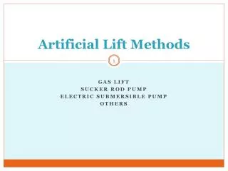
Gas Lift Optimization – Team Objectives Identify problem wells or common well problems Improving oil production rate Optimizing gas injection Reviewing well performance Maximize overall potential Stabilize oil production and gas injection
Contracted Job Titles OFFICE JOB – Gas Lift Engineer Gathering reservoir & production data Reviewing gas lift performance & current GL design Generating recommendations WORKSHOP JOB – GLV Technician Calibration and repair all gas lift equipment Manage gas lift equipment inventory & inventory reports FIELD JOB – Gas Lift Specialist Installing, tuning & troubleshooting GL wells Training company field operators (personnel) Coordinate gas lift activities with field supervisor
Oil Gain Contribution by Field Total oil gain = 3559 bopd
Diagnostic Tools To optimize gas dual lift well, complete information is required: • Well Case History • Three-Pen Static Pressure Recorder • Daily Production Record • Flowing and Static Pressure Survey • Flowing and Static Temperature Survey • Echo Meter Survey • Well File (Drilling, Well Schematic) • Latest GLV Design Report • Setting Pressure Report • Wire Line Job Report
Well Review by Team • Old Oil Field with more than 30 years old • High FGOR with 1000 : 1 or more • Low PI with only about 1 – 3 blpd / psi • Low Production with about 200 - 500 blpd • Low Static Pressure with average ~ 600 psi • Limited Casing Pressure with ~ 600 psi only • Flowing Tubing Pressure is about 180 psi • Shallow well - reservoir depth ~ 3000 ft TVD • Limited data (SBHP and PI is normally unknown) • Old wells - may have leaking valve or tubing • Some gas lift valves installed 5-10 years ago
Dual Gas Lift Design – Lessons Learned • Enough Kick Off (KO) and Operating (OP) Pressure to reach deepest point of injection is required • Differential pressure between KO and OP is ~10% of casing pressure, (or at least 50psi) to cover all unloading valves of both strings are closed when surface casing pressure is set at OP • Use graphical method to select best point of injection of both strings and best draw down (200-300 psi) of both strings • Calculate by computer setting pressure Ptro; select best port sizes and gas injection rate required • All pressure settings (Ptro) of unloading valves for both strings must be selected according to surface closing pressure • Surface closing pressure of both strings must be at least 20 psi above OP, and 10 psi less than KO • Avoid “gas robbing” - depth point of injection of both strings must be close or equal; same thing in port size
UXA-4S/L Well Schematic REDESIGN WELL Since mandrels were installed in well, optimization on this will be done by redesign. Main job is how to determine best point of injection of both strings for optimum draw down and to avoiding robbing. To perform this job, gathering complete information of both strings is required. Since SBHP data is old enough, and to ensure static pressure therefore SBHP survey is required to be performed.
Graphical Method UXA – 4L PRESSURE (psi) 500 1000 1500 FTP CHP 0 D E P T H Ft T V D 0.1 p s I / ft Casing Pressure FL 1000 #1 Tubing Pressure #2 2000 #3 0.45 p s i / ft #7 3000 Mid Perforation FBHP 1200 p s i 4000
Computer Program Results (UXA – 4L) NOTE: Third mandrel is designed with S/O, but existing #3 valve can not be pulled out, therefore #2 valve is opening and set with Ptro = 300 psi
Gain Results After Gas Lift Redesign Gas lift valves were calibrated in workshop, then installed; unloading of tubing strings was done with at least 650 psi as KO. After well unloaded, then gas injection rate was adjusted to maintain surface casing pressure at 640 psi, or OP. Following chart summarizes results after gas lift optimization: OPERATING PRESSURE: 640 psi
Gain Results After Gas Lift Redesign OPERATING PRESSURE: 640 psi Well had been shut in since March 1996, and back on line March 2002 after gas lift redesign.
Total Oil Gains After Well Work at BP-Indonesia NOTE: Gas lift is the biggest contributor (70%) of the well work jobs, which resulted in oil gain at NWJO; BP-Indonesia