Download
1 / 16
160 likes | 277 Views
Status of the Bologna scanning laboratory. G. Sirri for the Bologna Group*. Bologna Group: L. Consiglio (PhD), M. Cozzi, D. Di Ferdinando (PhD), G. Giacomelli, M. Giorgini, G. Mandrioli, L. Patrizii, M. Pozzato (PhD), M . Sioli, G. Sirri + 2 undergrad. students, 3 technicians.

E N D
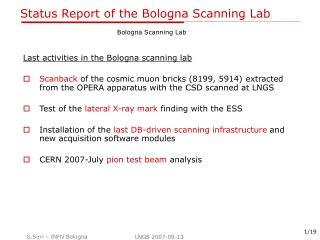
Status of the Bologna scanning laboratory G. Sirri for the Bologna Group* Bologna Group: L. Consiglio (PhD), M. Cozzi, D. Di Ferdinando (PhD), G. Giacomelli,M. Giorgini, G. Mandrioli, L. Patrizii, M. Pozzato (PhD), M . Sioli, G. Sirri + 2 undergrad. students, 3 technicians Nagoya 7-9 Dec 06
D043 D041 MIC 1 MIC 2 MIC 3 MIC 4 D042 D044 ntd 3 1 2 Bologna Emulsion Laboratory 4 2 air-conditioned rooms connected with the computing room (gigabit) Space for 2 automatic exchangers 4 microscopes all driven by the DB batch manager. • Prototype ESS – High ResolutionZeiss 100x oil objective • Vision/Motion Synchronization corridor • Standard ESS setup • Standard ESS setup • Standard ESS setup+ DRY objective Correction collar moving setup
MIC1: High Resolution • The microscope is equipped with : • ZEISS 100x objective | N.A. 1.3 • ZEISS tube lens hosted in a custom tube • Stage with higher load capacity [MICOS HPS-170] • Legs with air suspension mechanisms to reduce vibrations. • Custom CMOS camera (same sensor as mikrotron mc1310) • Motion/Vision synchronization using libACQ (by Bern) • Illumination, horizontal stage, motor controller, frame grabber, workstation are the same as ESS • This microscope is used for manual checks, fog density and grain size measurements and normal scanning. MIC1: parameters optimization for scanning with both SySal and libACQ acquisition software in progress. R&D for homogeneous immersion (oil condenser N.A1.4)
MIC4 : ESS with also NIKON DRY collar correction objective Nikon ELWD PlanFluor DRY objective • magnification: 40x (nominal) • numerical aperture: 0.60 • working distance: 1.8 mm • correction range: 0-2 mm A DC motor, drive belt and serial motor controller has been mounted in a Nikon microscope. SySal acq sw modified. Working conditions: two collar positions c.c. 0 for the TOP scanning c.c. 0.3 for the BOTTOM scanning The magnification depends (a bit) on the correction. The focal plane vertical position depends (largely) on the correction position (ΔZ~ 40 µm). MIC4 setup and the dry objective optimization in progress. Another prototype of collar handler is coming.
MIC2, MIC3 : ESSs ready for the October Run MIC2 and MIC3 ready for the October Run according to the specifications agreed within the scanning working group. How to improve the accuracy and stability of the measurements? f.e. how to deal with scanning in case of high fog emulsion sheet (as in the november cosmic rays test for CS-brick connection)? • Installation and test of new software modules (tracking, … ) • Test of new filters We suggest to take into account also some points, for example: - Motion/Vision synchronization during acquisition • Microtracks on-line rejection using adequate quality evaluators • Use focus data as guess for on-line shrinkage evaluation
Analyses in progress in Bologna • Peanut analysis: • BL044 • BL088 • Cosmic ray exposure (shielding and handling): • brick transportation unit validation • internal shielding • CS-brick connection (November c. r. exposure test) • Edge scanning with ESS dedicated talk (10’)
Peanut analysis: 4 bricks exposed at FNAL:
BL044 9x10 cm2 on plates 1-4 6x5 cm² on the plates 5-57 General Scan : • Rejected all vertices • whose tracks were not all downstream the vertex • Found 148 vertices • Required that at least one track from the vertex reaches the end of the brick. • 43 vertices
BL044 42 vertices are 2-prongs 1 vertex is 5-prongs
BL044 : Brick-SFT matching To validate the vertices : Match between SFT predictions and the 2 most downstream plates t.eTY The analysis is still in progress.
BL088 : Brick-SFT matching 90cm² general scan on the first three plates 298 tracks matched with SFT DB-driven ScanBack in progress.
Peanut summary BL044 General Scan of the brick completed (6x5 cm2 area) SFT-brick connection successful Vertex validation in progress BL088 Scan Back of SFT predictions in progress
C. R. exposure: Brick Transportation Unit As decided at the June PB, 20 boxes have been produced. Now the production has been stopped in order to: 1) validate them from the technical point of view 2) validate them from the scanning point of view • They have been used in the Nov test at LNGS (14 bricks exposed at the cosmic ray pit) 2) A special test was performed in October in order to guarantee the CSD-Brick mechanical compatibility (for transport BMSX ray site) - 4.75 day exposure inside the CR pit (outside the shielding) - exposure interrupted to stress the brick and the box (many opening-closing cycles, shakings etc.) - results: a) unique align pattern: bivariate gaussian with sqx~sqy~30 mrad b) integral number of tracks compatible with a 4.75 day exposure (after correction for efficiency ~ 85%)
C. R. exposure: Internal Shielding • The internal shielding is still pending to be validated: Oct run would be useful also for this; • Nevertheless, in the Nov test 14 bricks have been exposed in the cosmic ray pit in different experimental conditions: • 10 in the internal shielding • 3 outside the internal shielding • 1 outside the internal shielding and near the roof (as in the 2003 exposure – where we measured a penetrating component) • We would ask to the institutions involved in the test to provide a measurement of this quantity: basetrack density as a function of the emulsion sheet (after quality cut and inside a 400 mrad cone)
CS1 z = 300m CS2 z ≈ 4800m PL 60 PL 1 CS-brick 3000681 connection LNGS scanning of CS doublet provided 11 tracks Scanning of plate 60 in Bologna Fog: 15 / 1000 m3 Many electrons Microtracks / View: ~1600 BaseTracks / View: ~400 BaseTracks / View after quality cut*: ~50 *CHI2< 0.66*PULS-9 Found 18 base-tracks compatible with 8 LNGS trackswithin 200 m and 0.03*(1+3*|slope|) rad
CS-brick 3000681 connection Manual Check Search for tracks without taking into account the result of the automatic scanning Found 6 tracks Fine alignment of CS doublet and PL60 Search for the “missing” tracks found 3 more Final manual check result: 9 tracks found (2 LNGS tracks not found) 1.000932 0.001862 0.000650 0.999876 -62.987892 -60.705399 With the plate 60 located at z = -4976 Manual vs automatic scan:only 5 out of 8 tracks found with the automatic system are good Warning: it seems that the x-ray beams for marking is somewhat divergent