Download
1 / 18
180 likes | 309 Views
Programmable Controller Basics Advanced Instructions. MicroLogix Packaged Controllers. Advanced Instructions. SEQUENCERS SHIFT REGISTERS DATA HANDLING HIGH SPEED COUNTER SUBROUTINES. SEQUENCERS. First products were Electro-Mechanical designs.

E N D
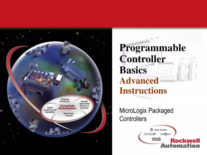
Programmable Controller BasicsAdvanced Instructions MicroLogix Packaged Controllers
Advanced Instructions • SEQUENCERS • SHIFT REGISTERS • DATA HANDLING • HIGH SPEED COUNTER • SUBROUTINES
SEQUENCERS • First products were Electro-Mechanical designs. • These devices were used to provide switch closure based on the position of a cylindrical drum. • “Programming” consisted of placing “Pegs” or “Pins” in holes, that in turn made contact with limit switches. • Program size and output capacity were derived from the physical size of the cylinder. “Long” drums provided more output capacity, “Large” drums provided for more program steps.
0 0 1 0 1 0 1 1 1 1 0 1 0 1 0 0 0 2 0 1 0 1 0 1 1 1 3 0 0 1 0 1 0 1 0 4 1 1 0 0 1 0 0 1 5 SEQUENCERS Peg Locations in Cylinder 1 2 3 Rotation 4 5 Bit Locations in Table
SQO SEQUENCER OUTPUT File #N:10 Mask 03F0 Dest O:0 Control R:1 Length 4 Position 3 EN DN SEQUENCERS
SEQUENCERS SQO Sequencer Output This is used to control specified outputs with an internal data table. SQC Sequencer Compare This is used to compare specified inputs with an internal data table and provide indication that a match was detected. SQL Sequencer Load This is used to load a word (16bits) into a selected position within an existing Sequencer
SHIFT REGISTERS USES: • Output Instruction • Store Data • Position or “track” status • Temporary Storage
11 7 6 14 13 12 10 9 8 5 4 2 15 3 1 0 11 7 6 14 13 12 10 9 8 5 4 2 15 3 1 0 11 7 6 14 13 12 10 9 8 5 4 2 15 3 1 0 “Bit” Shift Registers Are used to track or represent position during transport. Can be “stacked” to provide more information about the particular location.
TYPICAL SHIFT REGISTER APPLICATION PAINT SPRAY BOOTH SHIFT LIMIT SWITCH CONVEYOR INPUT LIMIT SWITCH SHIFT REGISTER 2 1 3 4 5 6 “Bit” Shift Registers
FFL FFU FIFO LOAD Source N:10 FIFO #N:12 Control R:1 Length 5 Position 4 FIFO UNLOAD FIFO #N:12 Dest N:11 Control R:1 Length 5 Position 4 EN EN DN DN EM EM Position 0 N:11 N:12 1 N:13 2 N:14 3 N:15 4 N:10 N:16 “Word” Shift Registers FIFO First In First Out
LFL LFU LIFO LOAD Source N:10 LIFO #N:12 Control R:1 Length 5 Position 2 LIFO UNLOAD LIFO #N:12 Dest N:11 Control R:1 Length 5 Position 2 EN EN DN DN EM EM Position 0 N:11 N:12 1 2 3 4 N:10 “Word” Shift Registers LIFO Last In First Out N:13 N:14 N:15 N:16
Data Handling MicroLogix and SLC processors support a wide range of data handling and manipulation instructions. • Data Moves (Moving data internally) • Data Manipulation (Mathematics, Square Root, Scale etc.) • Data Conversion (BCD, Integer, Decode etc.) • Data Comparison (<, <=, =, >=, >, Limit etc.)
MOV MOVE Source Dest Data Handling • Output Instruction • Organization of data • Position data
ADD ADD Source A Source B Dest Data Handling • Output Instruction • Mathematics • Data Formatting • Scaling (Engineering Units) (ADD, SUB, MUL, DIV, DDV, CLR, SQR, SCL)
XOR FRD BITWISE EXCLUS OR Source A Source B Dest From BCD Source Dest Data Handling • Output Instruction • Logic Functions (AND, OR, XOR, NOT, NEG) • Conversion (TOD, FRD, DCD, ENC, )
HIGH SPEED COUNTER • Output Instruction • Enhanced Capabilities • Asynchronous Output Control • 6.6 Khz (75us Pulse Detection)
HIGH SPEED COUNTER • Eight Modes of operation • UP • UP with external reset and hold • Pulse and direction • Pulse and direction with external reset and hold • Up and Down • Up and Down with external reset and hold • Encoder • Encoder with external reset and hold
HSC HSL HIGH SPEED COUNTER Type Enc Counter C5:0 High Preset 100 Accum 0 CU HSC LOAD Counter C5:0 Source N Accum 0 CU CD DN DN HIGH SPEED COUNTER Seven specialized instructions HSC High-Speed Counter Enable HSL High-Speed Counter Load RES High-Speed Counter Reset RAC High-Speed Counter Reset Accumulator HSE High-Speed Counter Interrupt Enable HSD High-Speed Counter Interrupt Disable OTE Update High-Speed Counter Image Acc