Download
1 / 14
140 likes | 339 Views
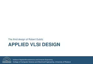
Automatic Design Optimization Applied to Lean Premixed Combustor Cooling. F. Duchaine 1 , L.Y.M. Gicquel 1 , T. Poinsot 2 , D. Bissières 3 and C. Bérat 3 1 CERFACS, Toulouse, France 2 IMFT, Toulouse, France 3 TURBOMECA, Bordes, France. 1.0. 0.9. Objective. 0.8. Initial guess. 0.7.

E N D
Automatic Design Optimization Applied to Lean Premixed Combustor Cooling F. Duchaine1, L.Y.M. Gicquel1, T. Poinsot2, D. Bissières3 and C. Bérat3 1 CERFACS, Toulouse, France 2 IMFT, Toulouse, France 3 TURBOMECA, Bordes, France
1.0 0.9 Objective 0.8 Initial guess 0.7 0.6 Optimization LOW NOx: Reduce flame temperature 0.5 0.4 lean combustion excess of air in the reacting zone CERFACS’ contribution 0.3 0.2 0.1 0.0 -30 -20 -10 0 10 20 30 FRT (%) 70% Total Air Mass flow rate premixed with fuel ONERA 30 % for cooling + control of the exit temperature profile Aim: reduce engineering costsby performing an automaticsearch of the optimal design of the cooling system. CERFACS Industrial context Automatic chain optimization for low Nox injection system and combustor
Important aspect: • To achieve all this, multiple codes must be coupled • The coupling tool used for this is a key process • For the CERFACS work, a coupling tool issued from the CERFACS’ Team Global Change is used: PALM Coupler PALM (http://www.cerfacs.fr/globc/PALM_WEB/) • Control of parallel codes • Parallel tasks • Friendly GUI (PrePALM) • Lots of functions (debug, algebra …) • Modular device (ensure evolutivity) • Efficient parallelism (MPI 2)
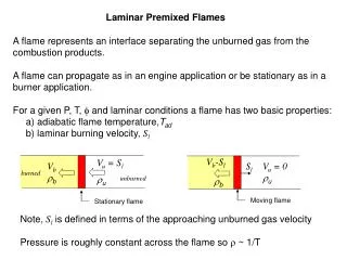
Computed exit temperature profile Estimation of the objective function New running parameters Target temperature profile TT (y) : Target temperature profile (user input) TC (y) : Computed temperature profile (CFD solution) Up to 10 optimization parameters: • BC: • VFB - TFB - VFC - TFC • Geometric: • LBB - DFD - LBC - DFC - aFB - aFC Validation configuration (example in a 2D configuration) Configuration representative of cooling process found in the dilution region of a combustion chamber Cooling LBB VFB TFB DFBaFB Fixed input: hot gas UCA = 30 m/s TCA = 1500 K DCA = 0.03 m VFC TFC DFCaFC LBC Cooling
Feasibility of dilution system optimization 1rst attempt : Simplex Algorithm + Coupling between the RANS code and an optimization algo. is possible within the CERFACS’ Coupler + Optimization loop tested and validated on academic tests with gradual difficulties (up to 5 optimization parameters) + Robustness of the approach: convergence was ensured even for hill posed situations (asymmetric target with fully symmetric optimization parameters) - The Simplex algorithm is not adapted to CFD-optimization and needs to be improved: Many CFD runs to converge to a local optimum (no surprise there !!) Use of surrogate model to reduce the limitation of a CFD run (time response / CPU time)
While Max Number of CFD runs Or Number of iteration reached Objective function Objective function Objective function Objective function Objective function Optimization parameter Optimization parameter Optimization parameter Optimization parameter Optimization parameter Optimization algorithm:Multiple start Quasi-Newton LBFGS(R.H. Byrd, P. Lu, J. Nocedal, and C. Zhu. A Limited Memory Algorithm for Bound Constrained Optimization. SIAM J. Scientific Computing 16, 5:1190-1208, 1995) Surrogate Model:Gaussian Process (called kriging: D.J.C. MacKay. Gaussian processes – a replacement for supervised neural networks? Lecture notes for a tutorial at NIPS. 1997) Actual work: Optimization assisted by surrogate model Space filling:Latin Hypercube Sampling(A. Giunta. Use of data Sampling, Surrogate Model, and Numerical Optimization in Ingenieering Design. AIAA, 2002-0538, 2002) N samples points = N CFD runs
Meta Model GP: Quick convergence Global convergence Actual work: Optimization assisted by surrogate model Exploration VS Exploitation • Global Meta model • Multiple start Gradient Algorithm • Use of merite objective function • Evolutive database • Accurate Meta model • Gradient Algorithm
Interpretation of design parameters to allow shape changes Surface re-meshing Surface mesh adaptation Smoothing techniques Smoothing techniques Interior grid adaptation Volume meshing Smoothing techniques Actual work: Optimization assisted by surrogate model Design Optimization : VS Re-meshing techniques Moving mesh techniques Parameterization of the initial shape and mesh
Pre-processing Pre-processing Pre-processing Parallel RANS Code Parallel RANS Code Parallel RANS Code Post-processing Post-processing Post-processing Actual work: Optimization assisted by surrogate model Parallel CFD tasks: • the proposed optimization solution allows independent CFD computations which can be done simultaneously. The coupler can take into account this request OP + MM or CFD + Tag Optimisation Simplex Genetic Algo. BFGS Surrogate … Meta Model Objective function value + Tag
Actual work: Numerical Results Configuration: 2D channel Cooling Fixed input: hot gas LBB VFB TFB DFBaFB UCA = 30 m/s TCA = 1500 K DCA = 0.03 m VFC TFC DFCaFC LBC Cooling Fixed parameters: VFB = -100 m/s TFB = 300 K VFC = 100 m/s TFC = 300 K DFD = 0.005 m DFC = 0.005 m aFB = 0 rad aFC = 0 rad • Target temperature profile obtained with a N3SNatur computation LBB = 0.075m and LBC = 0.05 m • Large deformation of the shape re-meshing techniques (J. Muller mesher: ipol and delaundo) Optimization parameters: LBB and LBC in [0.02 ; 0.15] m
Actual work: Numerical Results Optimum : LBB = 0.0771 m and LBC = 0.0429 m Evolution of the surrogate model : Initialization: 20 Objective Function Evaluations (LHS) After few iterations: 55 Objective Function Evaluations
Global Optimum : LBB = 0.075 m and LBC = 0.05 m 42 OFE 36 OFE Optimum Obtained with surrogate method: LBB = 0.0771 m and LBC = 0.0429 m • The surrogate method provides full information on the cost function over the domain : • local minima • general tendencies The Simplex method may get lost and provide a non-optimum solution When the Simplex method is well initialized, it only give the same result as the surrogate model Actual work: Numerical Results Comparison between Simplex optimization and surrogate approach :
Surrogate model: • Accurate results • Global optimization • Reduced CPU and clock time • Interpretable results: tendency of the fitness versus design variables Actual work: Numerical Results Comparison between Simplex optimization and surrogate approach :
Control of the shape Surface meshing Extension of Surface mesh to Volume mesh CFD runs On going work: 3D configuration 3D channel flow