Download
1 / 1
10 likes | 151 Views
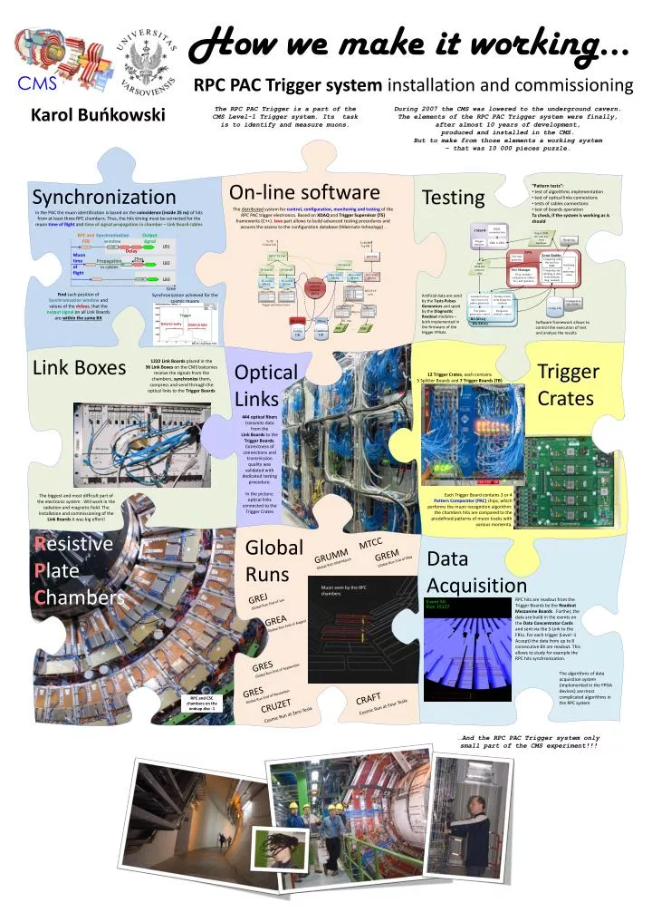
DQM, reconstruction. CMSSW. Output XML file with data from hardware. To TS Central Cell. Result log. To RCMS Top FM. XML to DIGI. Trigger emulator. RPCT TS Cell. RPC FM. JAVA. Event Builder. TS Subcell. Test data generator. Comparing with the test data XML.

E N D
DQM, reconstruction CMSSW Output XML file with data from hardware To TS Central Cell Result log To RCMS Top FM XML to DIGI Trigger emulator RPCT TS Cell RPC FM JAVA Event Builder TS Subcell Test data generator Comparing with the test data XML Analysing of interconnections or TS Subcell TS Subcell … input XML file with test data LBox access XDAQ LBox access XDAQ DCC access XDAQ Test Manager … Comparing and merging of data from different diag. readouts Monitoring and test manager JAVA TC accessXDAQ SC accessXDAQ Diag. modules configuration (delays etc.) and operation … VME DCC/CCS crate VME VME FEC FEC DCC … formation of test data vectors for pulses generators Parsing of data from diagnostic readouts Trigger and Sorter Crates CCU rings Config. DB Configuration file (XML) LBox’es … Test pulses generators control Diagnostic readouts control DB service TStore I2C rings HA XDAQ Condition DB Config DB FEB FEB FEB FEB … HA XDAQ How we make it working… RPC and FEB Synchronization window Output signal LB1 Delay Muon time of flight 25ns Propagationin cables LB2 Trigger CMS LB3 RPC PAC Trigger system installation and commissioning time Datato early Data to late Karol Buńkowski • The RPC PAC Trigger is a part of the CMS Level-1 Trigger system. Its task is to identify and measure muons. • During 2007 the CMS was lowered to the underground cavern. The elements of the RPC PAC Trigger system were finally, after almost 10 years of development, produced and installed in the CMS. But to make from those elements a working system – that was 10 000 pieces puzzle. BX of chamber hits On-line software Synchronization • “Pattern tests”: • test of algorithms implementation • test of optical links connections • tests of cables connections • test of boards operation • Ta check, if the system is working as is should Testing • The distributed system for control, configuration, monitoring and testing of the RPC PAC trigger electronics. Based on XDAQ and Trigger Supervisor (TS) frameworks (C++). Java part allows to build advanced testing procedures and assures the access to the configuration database (Hibernate tehnology) . • In the PAC the muon identification is based on the coincidence (inside 25 ns) of hits from at least three RPC chambers. Thus, the hits timing must be corrected for the muon time of flight andtime of signalpropagation in chamber – Link Board cables • Find such position ofSynchronization window and values of the delays, that the output signal on all Link Boards are within the same BX Synchronization achieved for the cosmic muons • Artificial data are send by the Tests Pulses Generators and spied by the Diagnostic Readout modules – both implemented in the firmware of the trigger FPGAs • Software framework allows to control the execution of test and analyze the results Link Boxes Trigger Crates 1232 Link Boards placed in the 96Link Boxes on the CMS balconies receive the signals from the chambers, synchronize them, compress and send through the optical links to the Trigger Boards Optical Links 12 Trigger Crates, each contains 5 Splitter Boards and 7 Trigger Boards (TB) 444 optical fibers transmits data from the Link Boards to the Trigger Boards. Correctness of connections and transmission quality was validated with dedicated testing procedure. In the picture: optical links connected to the Trigger Crates Each Trigger Board contains 3 or 4 Pattern Comparator (PAC) chips, which performs the muon recognition algorithm:the chambers hits are compared to the predefined patterns of muon tracks with various momenta. The biggest and most difficult part of the electronic system . Will work in the radiation and magnetic field. The Installation and commissioning of the Link Boards it was big effort! ResistivePlateChambers Global Runs MTCC Data Acquisition GREMGlobal Run End of May GRUMMGlobal RUnMid-March Muon seen by the RPC chambers GREJGlobal Run End of Jun RPC hits are readout from the Trigger Boards by the Readout Mezzanine Boards . Further, the data are build in the events on the Data Concentrator Cards and sent via the S-Link to the FRLs. For each trigger (Level -1 Accept) the data from up to 8 consecutive BX are readout. This allows to study for example the RPC hits synchronization. GREAGlobal Run End of August GRESGlobal Run End of September The algorithms of data acquisition system (implemented in the FPGA devices) are most complicated algorithms in the RPC system GRESGlobal Run End of November CRAFT Cosmic Run at Four Tesla RPC and CSC chambers on the endcap disc -1 CRUZET Cosmic Run at Zero Tesla • …And the RPC PAC Trigger system only small part of the CMS experiment!!!