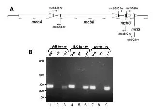
Download

1 / 32
320 likes | 460 Views
EWAP 800-C18 AJYNN. EWAP 800-C18 AJYNN. Air Cooled Chiller - Cooling Only 744 kW ÷ 1730 kW Single Screw Compressor. TABLE OF CONTENT. EWAP-AJYNN range Unit position into the range Technical solution Operating Limits Compressor features Refrigerant Circuit DX shell & tube evaporator

E N D
EWAP800-C18AJYNN Air Cooled Chiller - Cooling Only 744 kW ÷ 1730 kW Single Screw Compressor
TABLE OF CONTENT • EWAP-AJYNN range • Unit position into the range • Technical solution • Operating Limits • Compressor features • Refrigerant Circuit • DX shell & tube evaporator • Control & remote control • Unit delivery • Options summary • 1. Standard options • 2. Options on request
B. UNIT POSITION INTO THE RANGE (1/5) EWAP-AJYNN– Unit efficiency level 2.80 900 2.70 C10 C13 C14 C12 C11 C16 850 C15 950 2.60 C18 C17 2.50 EER 2.40 C13 900 C14 C15 C16 950 C17 800 C10 C18 C12 C11 2.30 2.20 EWAP-AJYNN EWAP-AJYNN/A 2.10 500 600 700 800 900 1000 1100 1200 1300 1400 1500 1600 1700 1800 1900 2000 kW
B. UNIT POSITION INTO THE RANGE (2/5) EWAP-AJYNN: cooling range EWAP- AJYNN 2 compressors 3 compressors EWAP- AJYNN +OPRN 2 compressors 3 compressors EWAP- AJYNN + OPLN 3 compressors 2 compressors 500 600 700 800 900 1000 1100 1200 1300 1400 1500 1600 1700 1800 1900 2000 kW cooling @ Evap. 12/7°C - 35°C OAT
B. UNIT POSITION INTO THE RANGE (3/5) EWAP-AJYNN/A: cooling range EWAP- AJYNN /A 2 compressors 3 compressors EWAP- AJYNN/A+OPRN 3 compressors 2 compressors EWAP- AJYNN/A + OPLN 3 compressors 2 compressors 500 600 700 800 900 1000 1100 1200 1300 1400 1500 1600 1700 1800 1900 2000 kW cooling @ Evap. 12/7°C - 35°C OAT
B. UNIT POSITION INTO THE RANGE (4/5) EWAP-AJYNN: sizes distribution 943 1284 1426 790 1091 1583 1026 1158 1353 1516 1650 875 822 963 1092 1271 1422 1547 744 887 1025 1205 1346 1484 744 1205 1484 887 1025 1346 963 1092 1271 1422 1547 822 EWAP-AJYNN EWAP-AJYNN+OPRN EWAP-AJYNN+OPLN 500 600 700 800 900 1000 1100 1200 1300 1400 1500 1600 1700 1800 1900 2000 kW cooling @ Evap 12/7°C - 35°C OAT
B. UNIT POSITION INTO THE RANGE (5/5) EWAP-AJYNN/A: sizes distribution 854 1027 1195 1357 1497 1644 1252 1427 1123 1594 1729 954 818 981 1137 1300 1423 1586 911 1069 1202 1365 1522 1649 1069 1202 1365 1522 1649 911 981 1137 1300 818 1423 1586 EWAP-AJYNN/A EWAP-AJYNN/A+OPRN EWAP-AJYNN/A+OPLN 500 600 700 800 900 1000 1100 1200 1300 1400 1500 1600 1700 1800 1900 2000 kW cooling @ Evap 12/7°C - 35°C OAT
C. TECHNICAL SOLUTION (1/4) EWAP-AJYNN version – Technical Solution Helicoidal fans (860 RPM) with good acoustic performance and no mechanical vibrations EWAP-AJYNN Compressor antivibration support to avoid transmission on chiller metal base-frame Rubber round washers to avoid metal to metal contacts which would increase chiller structural noise 80,5 ÷ 81,5 dB(A) ISO 3744 - @ 1m hemispherical field
C. TECHNICAL SOLUTION (2/4) EWAP-AJYNN + OPRN version – Technical Solution EWAP-AJYNN + OPRN Helicoidal fans with good acoustic performance and no mechanical vibrations Compressor antivibration support to avoid transmission on chiller metal base-frame Rubber round washers to avoid metal to metal contacts which would increase chiller structural noise 75 ÷ 77 dB(A) ISO 3744 - @ 1m hemispherical field Discharge flexible pipe to avoid vibrations in the condensing section of the chiller due to the gas pulsations and compressor vibrations Fan speed reduction ( 680 RPM) to reduce the noise level of the chiller condensing section
C. TECHNICAL SOLUTION (3/4) EWAP-AJYNN + OPLN version – Technical Solution EWAP-AJYNN +OPLN Helicoidal fans with good acoustic performance and no mechanical vibrations Compressor antivibration support to avoid transmission on chiller metal base-frame Rubber round washers to avoid metal to metal contacts which would increase chiller structural noise 72.5 ÷ 73.5 dB(A) ISO 3744 - @ 1m hemispherical field Discharge flexible pipe to avoid vibrations in the condensing section of the chiller due to the gas pulsations and compressor vibrations Compressor sound proof cabinet with aluminium frame, metal panels and high density material inside to absorb acoustic waves Fan speed reduction ( 680 RPM) to reduce the noise level of the chiller condensing section
D. OPERATING LIMITS (1/2) EWAP-AJYNN Unit Operating Limits OPRN OPLN Unit version EWAP-AJYNN °C 42 38 38 Max ambient temperature (at full load) °C +10 (2) +10 (2) +10 (2) Min ambient temperature °C 10 10 10 Max leaving evaporator water temperature °C 4 4 4 Min leaving evap. water temp. (without glycol) °C -8 -8 -8 Min leaving evap. water temp. (with glycol) D Max evaporator T °C 6 6 6 D Min evaporator T °C 4 4 4 Notes: When air temperature is lower than +10°c you need the fan speed control device. It allows the unit working with air temperature down to -10°c. OPLA allows to reach -18°c. (1)
D. OPERATING LIMITS (2/2) EWAP-AJYNN/A – Unit Operating Limits Unit version /A+OPRN /A+OPLN EWAP-AJYNN/A °C 46 42 42 Max ambient temperature (at full load) °C +10 (2) +10 (2) +10 (2) Min ambient temperature °C 10 10 10 Max leaving evaporator water temperature °C 4 4 4 Min leaving evap. water temp. (without glycol) °C -8 -8 -8 Min leaving evap. water temp. (with glycol) D Max evaporator T °C 6 6 6 D Min evaporator T °C 4 4 4 Notes: When air temperature is lower than +10°c you need the fan speed control device. It allows the unit working with air temperature down to -10°c. OPLA allows to reach -18°c (1)
E. COMPRESSOR FEATURES (1/3) EWAP-AJYNN – Single Screw Compressor “ Frame4 ” single screw compressor • axial balanced loads • radial balanced loads • 2 specular compression cycles • infinitely variable cooling capacity control • external oil separator • direct driven screw (no gear) • 6 electrical terminals for Y-D as standard • fully semi-hermetic design • composite material on gate rotors compression suction discharge
E. COMPRESSOR FEATURES (2/3) EWAP-AJYNN – Single Screw Compressor “ Frame4 ” radial balancing axial balancing better chilled water stability Composite material (carbon base composition) to improve compressor reliability and energy performances Stepless slide valve (oil controlled) to change compressor capacity to match exactly the plant thermal request
E. COMPRESSOR FEATURES (3/3) EWAP-AJYNN – Single Screw Compressor External high efficiency oil separator mounted on the same compressor metal base frame “ Frame4 ” Fully semi-hermetic design to allow ordinary maintenance and to replace easily each component if necessary Six electrical terminals to allow as standard a star-delta (Y-D) compressor start.
E. REFRIGERANT CIRCUITS EWAP-AJYNN – Truly Independent Refrigerant Circuits EWAP-AJYNN with 3 refrigerant circuits: 3 compressors, 3 expansion valves, 3 condensing sections, 3 evaporating sections in the evaporator’s shell, 3 dry-filters
E. DRY-EXPANSION SHELL AND TUBE EWAP-AJYNN - DX (Dry-eXpansion) shell & tube evaporator copper tube internally enhanced • One pass configuration on refrigerant side (R-407c) • Better oil circulation and compressor oil return at part load operation • Higher water volume content (Vs PHE Plate Heat Exchanger) • More thermal inertia for the chiller • Smaller external water tank installation (when required) • No freezing risk at any chiller load • No “water hammer” phenomena damage
F. CONTROL & REMOTE CONTROL (1/4) EWAP-AJYNN – Electrical Panel Features • Power and control are located in two different sections. • Main switch: only on OFF position, it allows the access to power section. • Control section opening is possible also when power is ON.
F. CONTROL & REMOTE CONTROL (2/4) EWAP-AJYNN – Microprocessor Control “Microtech II C Plus” Motherboard with microprocessors • Unit Controller fully programmed and engineered by Daikin on Carel hardware • P.I.D. logic (proportional, integrative, derivative) • Compressor regulated according leaving evaporator water temperature (LEWT) to match customer set-point within ± 0,2°C • Easy visual interface with 4 rows and 20 characters display and 15 keypad
F. CONTROL & REMOTE CONTROL (3/4) EWAP-AJYNN – Microprocessor Control “Microtech II C Plus” "demand limit" or "set-point reset" "current limit" from external signal SPN STANDARD "set-point reset" "soft load" from OAT • High value control functions implemented as standard into the logic
F. CONTROL & REMOTE CONTROL (4/4) EWAP-AJYNN – Microprocessor Control “Microtech II C Plus” • Easy integration into building automation systems via separate digital connection for unit start/stop and 4-20 mA signals for chilled water reset and demand limiting; • Communications capabilities for remote monitoring, changing of setpoint, trend logging, alarm and event detection, via a compatible IBM-PC with PlantVisor 2.0(EKPV2J) software; • BMS communication capability via Modbus, BacNet & LonWorks protocol • Remote communication via modem/GSM (up to 8 chillers with Gateway) • Compatibility with Daikin EKCSCII (Chiller SequencingControl)
I. UNIT DELIVERY (1/2) EWAP-AJYNN – Unit delivery, moving and lifting • Unit is delivered EXW (Ex works); • Each unit is tested at full load before shipping; • Unit handling must be according to IOM manual.
I. UNIT DELIVERY (2/2) EWAP-AJYNN – Unit delivery, moving and lifting Up to 14570 mm • EWAP950-C18AJYNN/A exceeds dimensions of a standard truck. • A “long vehicle” is necessary.
Standard options Brine version Dual setpoint Thermal relays compressors Under/over voltage controller Condenser Coils Alucoat Flow switch for evaporator Setpoint reset and demand limit Alarm from external device Rubber type antivibration mounts Evaporator heater Evaporator victaulics Main switch Electronic Expansion valve EWAP-AJYNN: OPTIONS SUMMARY (1)
OP57: A/V meter OPLN: Low noise OPGA: Gauges OPCG: Coil guards OPSS: Soft starter OPAL: Blank Cu/AI coils OPSN: Cu/Sn coils OPCU: Cu/Cu coils 1Not available for EWAPC15-18AJYNN and EWAPC15-C18AJYNN/A EWAP-AJYNN: OPTIONS SUMMARY (2) Options on request • OPSP¹: Single pump • OPTP¹: Twin pump • OPTR: Heat recovery • OPPR: Partial Heat recovery • OPHF: High ESP fans • OPRN: Reduced noise • OPFS: Fan silent • OPLA: Low ambient • OPPF: Power factor 0.9 • OP12: Suction stop valve Unit types • /A: high efficiency
1. OPTIONS AS STANDARD (1/2) ALARM FROM EXTERNAL DEVICE – Microprocessor is able to receive an alarm signal from an external device (pump etc…). User can decide if this alarm signal will stop or not the unit. FLOW SWITCH– Supplied separately to be wired and installed on the evaporator water piping (by others). COMPRESSOR THERMAL OVER RELAYS – Safety devices against compressor motor overloading in addition to the normal protection envisaged by the electrical windings.
1. OPTIONS AS STANDARD (2/2) UNDER/OVER VOLTAGE CONTROLLER –Phase monitor to control the minimum and maximum voltage value that the user can set. RUBBER TYPE ANTIVIBRATION MOUNTS–Supplied separately, these are positionned under the base of the unit for “floor installation”. ALUCOAT CONDENSER COILS – Fins are protected by a special acrylic paint with a high resistance to corrosion. EVAPORATOR ELECTRIC HEATER – Electric heater controlled by a thermostat to protect the evaporator from freezing down -28°C ambient temperature. ELECTRONIC EXPANSION VALVE –It proposes features that makes it unique: short openning and closing time, high resolution, positive shut-off function to eliminate use of additional solenoid valve, highly linear flow capacity, continous modulation of mass flow without stress in the refrigerant circuit and corrosion resistance stainless steel body.
2. OPTIONS ON REQUEST (1/3) OPSP: Water circulation pump– The pump is unit mounted. Hydronic kit consists of: one centrifugal pump direct driven, expansion tank, water feed circuit with pressure gauge, safety valve. The pump motor is protected by a circuit breaker installed in control panel. The kit is assembled and wired to the control panel. OPTP: Two water circulation pumps– The pumps are unit mounted. Hydronic kit consists of: two centrifugal pumps direct driven, expansion tank, water feed circuit with pressure gauge, safety valve, check valves, shut-off valves. The pumps motors are protected by circuit breakers installed in control panel. The kit is assembled and wired to the control panel. OPTR: 100%Total heat recovery–Produced with tube bundle placed in a single shell with the water condensers heads are provided with 2 connections for entering/leaving heat recovery water and 2 separate connections for condensing water.
2. OPTIONS ON REQUEST (2/3) OPPR: Partial heat recovery–Produced with plate to plate heat exchangers installed on discharge side of compressor gas. These allow hot water to be produced up to a maximum temperature of +50°C. OPFS device: Fan silent–This device allows the continuous variation of the fan speed, modifying the air flow according to the external temperature conditions. It allows the unit working with air temperature down to –5÷–10°C. In addition, a microprocessor clock switches the fan at low speed according to the client setting (i.e. Night & Day). OPLA: Low ambient– Continuous fan speed modulation on the first fan of each circuit. It allows the unit working with air temperature down to –18°C. OPPF: Power factor 0.9–Capacitor power factor correction - Installed on the electrical control panel to ensure it conforms to the plant rules.
2. OPTIONS ON REQUEST (3/3) OP12: Suction line shut off valve– Suction shut-off valve installed on the suction port of the compressor to facilitate maintenance operation. OPCG: Coil guards– Metal protection guards fixed on all the external surface of the condenser coils. OP57: Ammeter and voltmeter– Digital meters of unit drawn amperes and voltage values, installed on the electrical control panel. OPSS:Soft start–Electronic starting device to reduce starting current. An overload protection is included (no need of compressors thermal relays). OPCU – To give better protection against corrosion by aggressive environments. OPSN (new option)– To give better protection against corrosion in aggressive environments and by salty air.