Download
1 / 7
70 likes | 180 Views
6. C ONSTRUCTION S IMULATION. Objective: To understand the principles of computer-based construction simulation, and to develop expertise in applying the CYCLONE simulation method to construction planning: Summary: 6.1 Introduction 6.2 The CYCLONE Method

E N D
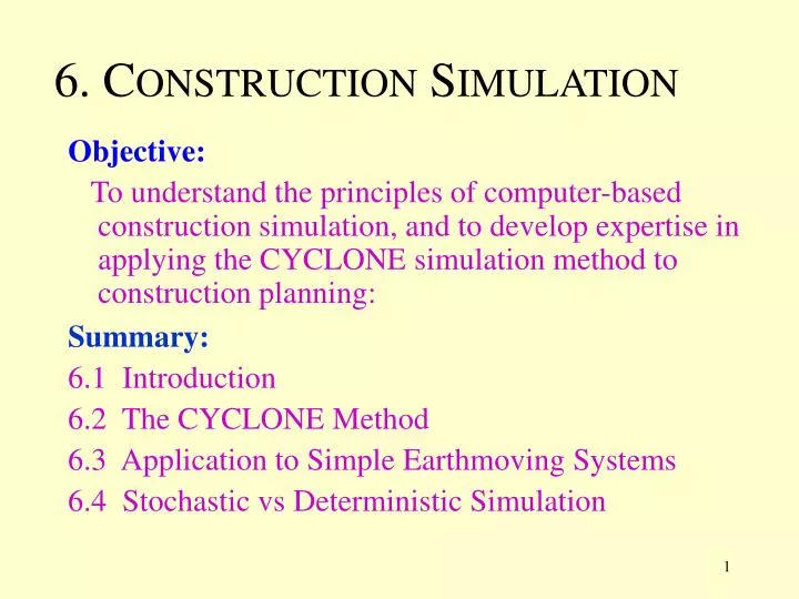
6. CONSTRUCTION SIMULATION Objective: To understand the principles of computer-based construction simulation, and to develop expertise in applying the CYCLONE simulation method to construction planning: Summary: 6.1 Introduction 6.2 The CYCLONE Method 6.3 Application to Simple Earthmoving Systems 6.4 Stochastic vs Deterministic Simulation
State 1 State 2 State 3 State 4 The 3-phase algorithm advances the model from its state at one point in time to its state at the next point in time: Fig. 6-1:Simulation as a Dynamic Modeling Technique 6.1 INTRODUCTION • Simulation is a dynamic modeling tool: • it mimics the processes on site as a sequence of snapshots (called system states); • this makes it very versatile (can in principle take any factor into account); • you cannot miss out states (the only way to find the end state is to go through all intermediate states); • each state is computed from the previous state using a 3-phase algorithm. 3 phase algorithm 3 phase algorithm and so on … A state is a snapshot of the system at a given point in time, for example: how much concrete is in a truck, location of a scraper on a haul road, the time of day, etc… phase 1: determine the next point in simulation time, and advance the simulation clocks: (eg: update the remaining duration for a truck traveling on a haul road); phase 2: update the state of each component to match the new point in time: (eg: update the amount of concrete in the foundation); phase 3: decide what will happen over the next period in time: (eg: if a truck has dumped its load, should it now start to return to the excavator or go for refueling?)
Applications: • Planning the effective use of resources: • How many trucks to use; • What capacity concrete mixers to minimize duration; • Designing and improving construction methods: • Whether to use cranes with skips or concrete pumps to pour concrete; • FIFO (first-in-first-out) queues, or serve trucks with the largest capacity first; • Estimating probable project durations. • Estimating the influence of unforeseen circumstances on progress. • Monitoring and controlling work in progress.
The NORMAL activity: this is performed by productive resources (equipment, crews, etc..) and it typically takes time to perform. The COMBI activity: this is similar to the NORMAL activity, except that it requires a resource to be available on every preceding queue node. A resource is taken from each preceding QUEUE NODE and combined into 1 resource for the execution of the activity. It can only be preceded by QUEUE NODES. The QUEUE NODE: this represents a point in a system where productive resources may have to wait to be processed. A resource will wait here until it can be combined with a resource from each of the other QUEUE NODES preceding a COMBI activity. An important function associated with this component is GEN which splits an arriving resource into several resources. The FUNCTION NODE: this performs simple functions, an important example of which is to consolidate arriving resources into a single resource (the opposite of the GEN function). The ARC : this connects the above components, defining the flow of resources through the system. 1 resource is output from every ARC leaving a component. The ACUMULATOR : this measures system productivity at a specific location. Fig. 6-2:Main CYCLONE Modeling Components 6.2 THE CYCLONE METHOD
Haul Return to start of cut Push load Dump Return Wait for scraper Wait for bulldozer 1bulldozer at start 3 scrapers at start Fig. 6-3:Simple CYCLONE Scraper Based Earthmoving Model 6.3 APPLICATIONTO SIMPLE EARTHMOVING SYSTEMS BULLDOZERCYCLE SCRAPERS CYCLE
Sleu CON 10 Haul Dig load Dump GEN 10 Return Repair Wait for dump truck Wait for excavator Sleu back 5 dump trucks at start (15 cu yd capacity each) 1 excavator (1.5 cu yd bucket) Fig. 6-4: CYCLONE Excavator-Truck Based Earthmoving Model In this system, the excavator must perform 10 cycles to load one truck EXCAVATORCYCLE DUMP TRUCKS CYCLE p = 0.95 p = 0.05
Permit to cross bridge (1) permit is released for next truck Sleu CON 10 Cross bridge Dig load Dump Haul EXCAVATORCYCLE Return DUMP TRUCKS CYCLE Wait for permit Wait for dump truck Wait for excavator Sleu back GEN 10 5 dump trucks at start (15 cu yd capacity each) 1 excavator (1.5 cu yd bucket) Fig. 6-5: CYCLONE Permit System In this system, the truck needs a permit to cross a bridge. This is to limit the bridge to one truck at a time.