Download
1 / 46
460 likes | 462 Views
Tracker Trigger System. Marvin Johnson for the Tracker Trigger Group October 2009. Tracker Trigger Group. Current members U. Heintz , M. Narain from Brown U. E. Hazen, S. Wu from Boston U. M. Johnson, R. Lipton from FNAL. Very interested in getting new members. Outline.

E N D
Tracker Trigger System • Marvin Johnson for the Tracker Trigger Group • October 2009
Tracker Trigger Group • Current members • U. Heintz , M. Narain from Brown U. • E. Hazen, S. Wu from Boston U. • M. Johnson, R. Lipton from FNAL. • Very interested in getting new members
Outline • This talk will cover the on detector part of the design • Trigger sectors • modules • getting the data off of the detector • Following talk by U. Heintz will cover off detector processing
Definitions • Stub: 2 hit track from a stack • Tracklet: 4 hit track formed from 2 stubs on a rod • Track: Combination of at least one tracklet and some stubs Stub Tracklet
Stubs • Required to get the hit rates down • Stack design allows local high bandwidth connection between pairs of sensors • Rate after stub finding allows data to be sent some distance for further processing
Why Tracklets? • Consider 3 layers and no tracklets (track hits but no Pt) • To find tracks need to test all combinations of tracks from all layers (minimum Pt covers entire sector) • Must be completed in 25 ns. • Tracklets allow projection of the track hit from one layer to another • reduces the range to check in the destination layer • All hits can be compared simultaneously in an FPGA • Practical limit is ~10 hits/layer • Subdivide layer to stay within this limit Tracklets allow reduced scan range 3 track 3 layer example
Goals and Constraints • Develop a robust track trigger for SLC upgrade • find high pt tracks • identify isolated tracks • 2.4 GeV/c minimum Pt • Hardware • Current gate array technology to test ideas • Easy to scale to larger devices • Optical link rate < 10 GB/sec
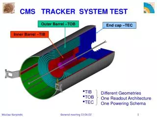
Tracker • Based on long barrel design but not restricted to long barrel design • Layers 3 and 4 extend eta reach • Map 3 and 4 to outer layer • Logically this reduces the long barrel to a 3 layer design
End View Sensor overlap so no communication between rods
Cornell Simulations • Track stubs from stack (/crossing/cm^2) • <.01 inner layer • . <.001 outer layer • Factor of 2 - 3 drop with Z (along rod) • Tracklets (from 2 stubs) • About a factor of 2 reduction from stub rate • Large drop with Z distance Stubs inner & Outer layers Tracklets inner & outer layers
Rates • Simulations likely underestimate rate • Increase Cornell rates by a factor of 10 • Monte carlo imperfections • Fluctuations in track density • Keep Z rate dependence • Reduces fiber optics and power at large Z • Reduces mass at ends where mass is increasing (cos affect)
Simple Basic Idea • Put all hits into a FPGA • Tracklets (from layers) or stubs (from stacks) • Put all possible track equations into the FPGA: layer a AND layer b AND layer c ... • Tracks come out one clock cycle later.
Practical Limits • Too many equations for single FPGA • Requires too many high speed serial lines for single FPGA • All track data must be loadable into an FPGA in one crossing (25 ns) • Trigger hits must also be sent out at the same time • Must spread problem over several FPGA’s
Trigger Sector • Minimum Pt is 2.4 GeV/c • Trigger element is 0.1 mm by 2 mm • 7 rods • 4 outer, 2 middle, 1 inner • Minimum Pt has big impact on hardware design 15 degree sector
R Z Geometry cont. • Z segmentation is needed for tracklets (rates) • Finite interaction region requires data from 2 longitudinal stacks in a rod • need stack to stack communication • complicates rod design if tracklet formation is on rod • This design forms tracklets off detector
R Phi Geometry • 15 degree sector matches 100 by 100 mm sensors (1, 2 and 4 rods/layer) • 1100 mm radius sets minimum Pt=2.4 Ge/V • Need to process data from both adjacent sectors to get all track data in home sector • Even more track equations than for one 15 deg sector
Equations • Too many equations for single FPGA • Too many fiber lines for a single FPGA • Sending data between FPGA’s is limited by FPGA pin count • Need to segment the data at the detector level • Tracklets allow this
Solution • Divide Outer layer into 12 segments • 36 segments for 3 sections • Tracklets from inner 2 layers are projected to outer layer segment • Outer layer uses stubs • Reduces effect of hardware failures • Segments must overlap due to imprecise projection
Repeat for Middle Layer • Missing stack in middle layer eliminates middle layer tracklet • Middle layer segmentation can use the stub • Recover half the information in the layer • Do the same for the inner layer • Must remove duplicates
Robust Design • Finds tracks: • With tracklets in all 3 layers • With tracklets in 2 layers + 0 or 1 stub • With tracklets in 1 layer plus 0, 1 or 2 stubs • Found Tracks tagged with tracklet info. • Specific trigger could require minimum number of tracklets and/or stubs
Detector Design • Send track stub data off detector • forming tracklets on detector requires stack to stack communication • Data rates show that this is feasible • inner layer has 8 hits per 100 cm^2 sensor/crossing • rate is a factor of 10 over Cornell simulations • At 20 bits/ event this is less than 7 GB/sec • More on this later
100 by 100 mm sensor with 16 chips • Communication from stack to outside world is difficult • 100 mm by 100 mm sensors requires 16 chips • set by reticle size • The 4 inner chips have no exposed edge • Central top and bottom conflict with adjacent sensors • Also need chip to chip link for track finding
Kapton Bus • Best solution seems to be a Kapton bus • DC-DC converter • Fiber Driver Chip • by pass capacitors • temperature monitoring ... • Buss is between interposer and chips • may be part of interposer 23
Yellow block is one sensor Blue is read out chip Tan is Kapton buss • Divide buss in center of sensor • Readout half buss on either side of sensor • short path for bypass capacitors and buss • Max rate is 8 tracks per crossing • 20 bits/track =>6.4 GB/s • 1 fiber per sensor • read out 2 half sensors/fiber Green+red is DC-DC converter Light blue is fiber driver
Green is carbon fiber support Yellow is sensor Red is interposer blue is read out chip • Don’t need full bandwidth over entire rod • Rate drops by half at half distance from IP in inner layer • Design optic chip with 4 inputs • use one chip to read 4 half sensors in outer part of inner layer • one chip per 8 half sensors in outer layers • Connector through carbon f rod • Minimizes mass By pass caps Tan is Kapton buss green-red is DC-DC blue is fiber driver
3 Rod End View Space for fibers and DC-DC is limited Inside CF is free but difficult to use 26
GBT Fiber Driver • Current GBT is 2 Watts and 3.6 GB/s • Save 40% of power by going to unidirectional transmission • Give up down load and control path to save power • Good clock still required • Reduce 16 bit error correction to 1 bit raises bandwidth to 5 GB/s • Go to 90 or 65 nM technology for added power reduction • ~1 Watt at 8 GB/s.
Tracklets • Processing done off detector • Use Z information • Sensor overlap in phi so no rod to rod communication needed • Optimized layout is 30 fibers for the inner layer • Fits into current FPGA (44 inputs at 10 GB/s) • Eliminates need for sensor overlap at z=0 • The next talk will cover the off detector processing
Summary • Tracklets allow layer segmentation so can do track finding in an FPGA • Multiple layers create a robust design • Simultaneous track finding in all 3 layers allows use of track stubs providing that there is at least one tracklet • Optimized GBT reduces both mass and power
Tracklet Processing • Must do all processing in 25 ns • Need information from top and bottom stack plus neighboring stacks for Z overlap • Problem divides into 21 (inner layer) pieces with some inter stack communication in Z direction • 160 bits per event per stack so all fits into FPGA registers (8 tracks @20 bits/track) • Compare all hits between stacks simultaneously • compare in both phi and Z • z range restricted by length of IP, phi range restricted by min. Pt
Tracklet Bandwidth • Simulation shows tracks are half the stub rate • Safety factor of 10 included fluctuations • Fluctuations should be less over entire rod • Use safety factor of 6 • track density drops faster than stub density with z • use same density as for stubs (conservative) • 40 Tracks/rod @30 bits/track = 48 GB/s
Tracklet Output • Sort tracklets by destination segment and send over dedicated fiber line • 12 segments/sector times 3 sectors =36 fibers • 48 GB/s is divided among 36 fibers so 8 GB/s fiber is OK • Project to 2 different layers so get another factor of 2 • 72 eight GB/s fanout from tracklet forming FPGA. Segments must have overlap to account for projection errors
Segment Processor • Receive sector data from 2 layers in 3 trigger sectors plus home layer • one fiber/rod/layer/sector: for inner and middle layers: 6 rods times 3 sectors or 18 fibers plus 1 for home fiber = 19 fibers plus 1 for trigger output • Need to compare all possible combinations of input tracklets so need all tracklets in registers in FPGA • 3 times 40 tracklets/layer = 120 tracklets in 12 segments • 10 tracklets/segment times 30 bits = 300 bits so OK • Output tracks ordered in Pt - highest first
Duplicate Eliminator • Find tracks in all 3 layers simultaneously • Must remove duplicate tracks • Receive data from 12 segments times 3 layers or 36 fibers • Tracks ordered in Pt so search is easy • Output tracks on perhaps 4 fibers
Pipelined Stages Tracklet • Load in stub data from sensors • Form tracklets from stubs • Sort tracklets by destination segment number • Send over fiber to segment processor
Pipeline Stages Segment Processor • Receive tracklet data from all 3 layers • Find tracks • Send data to duplicate eliminator
Pipeline Stages Duplicate Eliminator • Receive track data from all 3 layers • Compare all inputs and eliminate dulicates • Send track data to L1 trigger • 10 total pipe line stages for tracker trigger system
FPGA Capacity • Doubling FPGA capacity: 12 segments=>6 • Doubling IO capacity: 44 lines => 88 • Tracklet processor • 6 segments requires only 36 input lines • Tracklet input requires 30 lines and output 36 so it would fit • Segment processor and duplicate eliminator are not changed
Trigger and Down Load(Unidirectional GBT) • Down load is infrequent and slow • Single twisted pair cable should work. • Trigger and clock are common to all sensors • Optical link to tracker end • Twisted pair on rod • Could put additional link at mid point of rod if needed
Track Data • Readout event rate is .0025 of trigger rate at 100 Kz trigger rate • Factor of 10 larger event size would take 2.5% of the fiber band width. • Put data on the fibers from the sensors and separate it out in the tracklet forming chip
Optics Power • 30 fibers in inner layer sector • Number of tracks is about the same so should get all 3 layers in 90 fibers. • Add 10 fibers each for the 2 short barrels • 24 sectors gives 2640 fibers @ <1 watt/driver ~ 2.5 KW
System Advantages • Robust System • Example: lose a stub in inner and outer layer • Still form track with middle layer tracklet and stubs in inner and outer layer. • Easy scaling with bigger gate arrays • One sensor or chip failure does not disable the trigger in that part of a layer
System Drawbacks • Very large number of high speed links • Many single fiber connections • Reliability • Mass • Problem is significantly more difficult if rate estimates are too low • Get better estimates after LHC start up
Summary • Getting all required data into one place is an important constraint • Very large number of high speed links • Reliability • Power • Not constrained by FPGA size. • 2 layer design is simpler but it still has many of the same issues