Download
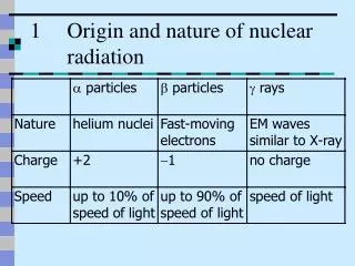
1 / 23
230 likes | 394 Views
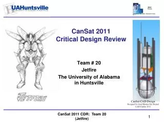
Critical Design Review “The Distribution of Ionizing Radiation with Altitude”. Left to Right: Izzy S.- Audio Visual Tom L.- Payload James Z.- Construction Dr. Marintsch - Head Mentor Youssef B.- Program Manager Paul T. - Rocket design Randall H. - Safety

E N D
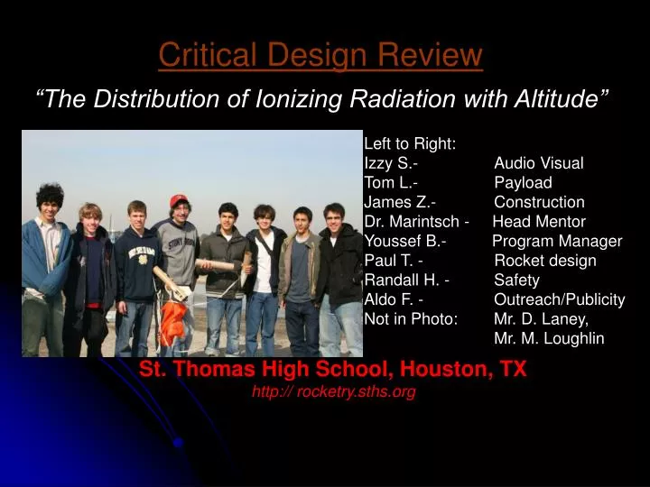
Critical Design Review “The Distribution of Ionizing Radiation with Altitude” Left to Right: Izzy S.- Audio Visual Tom L.- Payload James Z.- Construction Dr. Marintsch - Head Mentor Youssef B.- Program Manager Paul T. - Rocket design Randall H. - Safety Aldo F. - Outreach/Publicity Not in Photo: Mr. D. Laney, Mr. M. Loughlin St. Thomas High School, Houston, TX http:// rocketry.sths.org
Agenda • Mission Statement and Goals • Project Update • Launch Vehicle and Payload Summary • Vehicle Body System • Propulsion System • Recovery System • Payload System • Scale Launch • Payload Experiment • Planning of System Tests • Safety • Budget and Outreach
mission statement and goals Mission Statement Our mission is to supply accurate data about cosmic radiation by building a safe and functioning rocket that can provide ample time for data collection. Goals •Reach an altitude of one mile. •Payload records data on ionizing radiation. •Both parachutes deploy at predetermined altitudes. •Land within one square mile. •Rocket retrievable with payload intact. •Shed light on radiation variation with altitude.
Project update Work done since PDR • Removed canards and shortened the fins in the rocket design • Built and successfully launched the scale model • Testing of rocket electronics • Successful usage of dual deployment • Established a plan with the school advancement office for acquiring funds from school alumni Work still to be done • Building full-scale rocket • Modifying fins • Setting up payload • Fiberglass the tubes
launch vehicle and payload summary Vehicle: Length - 90” Mass with Motor - 10,078 g Diameter - 5.40” Stability Margin - 2.53 Motor - K560W Launch System - 1.5”x1.5” (10’) Recovery: Drogue – 28” at Apogee Main – 120” at 1500 ft. Payload Experiment Summary: Measure levels of cosmic radiation with altitude through the use of Geiger Mueller Tubes whose data will be correlated with time and altitude.
SYSTEMS Vehicle Body Propulsion Recovery Payload
(1) Vehicle Body System |---------------------------------------||--------------------------------||------------------------------------| Nose Cone & Upper Body Tube Middle Body Tube (Payload) Lower Body Tube •Modified LOC Precision Magnum 3e •Three Body Tubes (5.40”- size needed for payload) Lower (31”) – K560W, Drogue, G10 Fins, Camera Middle (28”) – Payload Bay Upper (11”) – Main Chute •Nose Cone (21”) GPS Transmitter
(2) Propulsion System •Motor: Aerotech K560W •Thrust / Weight: 5.7:1(Thrustcurve) [560N / (10 kg x 9.8m/s2)] 5.1:1(Rocksim) [497N / (10 kg x 9.8m/s2)] •Velocity off Launch Rod: 59.3 ft/s •Rail Length: 10 ft •Burn Time: 4.6 s
(3) Recovery System Drogue Chute • 28” LOC Precision • Deployed at Apogee (18.8 s) Main Chute • 120” Public Missiles • Deployment at 1500 ft (70.8 s) Redundancy Plan • 2 Perfectflite Dual Deployment Altimeters • Each one will connect to a drogue and main ejection charge Landing • Landing at 162 s • Velocity at Landing: 16.8ft/s(V); 10.3ft/s(H); 19.7ft/s(M)
(4)Payload System Top view Side view
(4)Payload System Within Middle Body Tube •Bay #1 - Geiger Mueller Tubes with Circuit board and Processor. •Bay #2 - Gamma-Scout Geiger Counter. •Bay #3 - Two Altimeters – Linked to ejection charges at either end of Payload Bay. Within Nose Cone •GPS Transmitter Outside of Lower Body Tube •Video camera
Scale Model • ½ Scale • G80 motor Launched with • 2 Perfectflite Dual Deployment Altimeters • Booster Vision camera Results • Reached an altitude of 1098 ft. • Successfully deployed 2 parachutes Scale Launch
payload experiment Hypothesis After consideration of the effects due to terrestrial radiation, we would expect the counts to increase with elevation as the net absorption of Secondary Cosmic Radiation by the atmosphere decreases.
payload experiment • Full scale tube array construction • Testing of GammaScout • Planned tube array design • Prototype array of five tubes
payload experiment Significance (1) Radiation is measured with altitude using 12”-long Geiger Mueller Tubes expected to record up to nearly 500 cpm over 140 s of descent and 19 s of ascent. (2) Radiation levels are suggested to be associated with changes in atmospheric conditions (such as cloud formation and global warming; chlorine production and ozone depletion) (3) Radiation levels are linked to the breakdown of DNA in organic tissue and so merit further study.
payload experiment Electronic usage Gamma Scout – Because of a long measurement interval time, the GammaScout will primarily be used for calibrating the Geiger Muller tube array Tube Array- Will be used as our primary data source when interpreting and graphing the data.
System testing Tested •GPS – Locality tracking. •Camera – Video testing. •Vehicle – Scale model launch. Testing •Payload – Geiger Counters and (a) consistency of data collection, (b) background counts, (c) isolation of ray sources. Will Test •Recovery – Ejection charges and chute deployment. Safety and RF Signals. •Propulsion – (a) Inspection of parts, (b) assembly supervision.
safety plans Prior to each project phase: Review system risks and mitigations. Review Safety Codes. Pass test on Safety Procedures. Sign Safety Statement.
budget and outreach Budget Current major purchases • Geiger Counter with data storage ($445) • Rocket Parts ($295) • Geiger Mueller tubes ($200) • GPS System ($450) • 120” parachute ($190) • Video camera ($100) Subtotal $1680 Imminent Purchases • Five additional GM tubes ($570) Subtotal $570 Outreach • Collaboration with school advancement office • Current preparation of Informational Flyers/Brochures. • Formulation of presentation/workshop strategies.