Download
1 / 106
1.07k likes | 1.27k Views
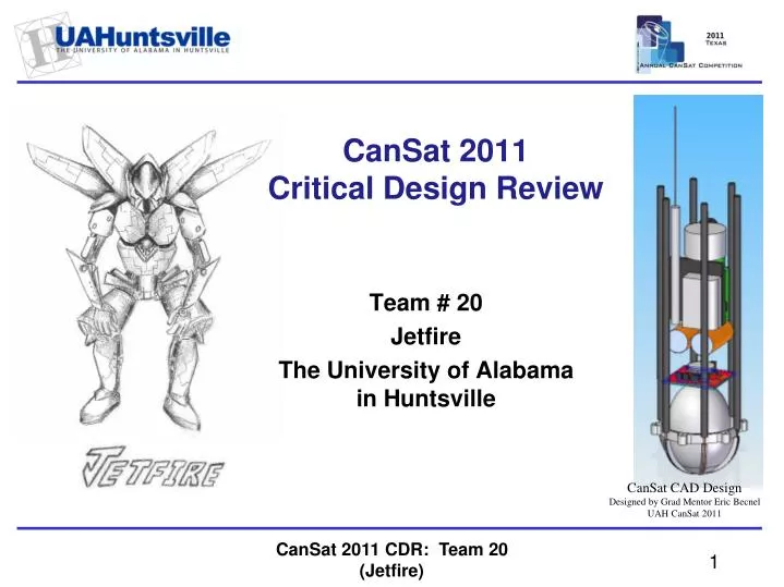
CanSat 2011 Critical Design Review. Team # 20 Jetfire The University of Alabama in Huntsville. CanSat CAD Design Designed by Grad Mentor Eric Becnel UAH CanSat 2011. Presentation Outline. Egg Drop Module Designed by Team Leader John Alcorn Fabricated by Grad Mentor Eric Becnel

E N D
CanSat 2011Critical Design Review Team # 20 Jetfire The University of Alabamain Huntsville CanSat CAD Design Designed by Grad Mentor Eric Becnel UAH CanSat 2011 CanSat 2011 CDR: Team 20 (Jetfire)
Presentation Outline Egg Drop Module Designed by Team Leader John Alcorn Fabricated by Grad Mentor Eric Becnel UAH Student Shop, CNC Milled Systems Overview Sensor Subsystem Design Descent Control Design Mechanical Subsystem Design Communication and Data Handling Subsystem Design Electrical Power Subsystem Design Flight Software Design Ground Control System Design CanSat Integration and Test Mission Operations & Analysis Management Presentation Scoring & Additional Information Questions? CanSat 2011 CDR: Team 20 (Jetfire) Presenter: John Alcorn
Team Organization • MAE ChairDr. Frederick • Faculty AdvisorMr. Troy Skinner • Graduate MentorEric BecnelMAE Grad Student • CanSat Project LeaderJohn AlcornMAE Freshman • Descent ControlJennifer HuntMAE Senior • Systems EngineerMark BecnelMAE Senior • Programming & Communications Systems • Nathan Newcomb, CPE SeniorMax Avula, CPE Grad Student • System ModelingStewart King, MAE FreshmanCaleb Lindsey, MAE Senior • Electrical SystemsTetsuya ToyamaEE Grad Student CanSat 2011 CDR: Team 20 (Jetfire) Presenter: John Alcorn
Acronyms CanSat 2011 CDR: Team 20 (Jetfire) Presenter: John Alcorn
John Alcorn Systems Overview CanSat 2011 CDR: Team 20 (Jetfire)
Mission Summary CanSat a payload that is carried by rocket to approximately 1km and ejected. made of two systems, a Carrier and Lander. The carrier is the primary component, which mid-descent deploys the Lander unit. Carrier System Ejects the Lander 500 m above the ground Maintains 4 m/s descent rate following Lander ejection Records and transmits live telemetry data during and after flight Beacons an audible signal upon landing Lander System Carries a large egg safely through flight Maintains 5.5 m/s descent rate following ejection from the Carrier Stores all telemetry data onboard Records impact force CanSat 2011 CDR: Team 20 (Jetfire) Presenter: John Alcorn
Carrier and Lander Sub-Systems Mission Summary Prototype Lander Nose Cone Designed by Descent Control Jennifer Hunt UAH Student Shop, Rapid Prototyped • Sensor Design • Sensor Testing • Mechanical Design and Fabrication • Egg Protection Testing • Ground Station Tower Design • Electrical Design and Fabrication • Sensor Wiring • Power System • Command and Data Handling • Sensor Data Handling • Radio Transmission • Ground Station Programming • Radio Reception • Graphical User Interface • Data Analysis • Post-Recovery Data Recovery and Analysis • Descent Control Design and Fabrication CanSat 2011 CDR: Team 20 (Jetfire) Presenter: John Alcorn
Summary of Changes Since PDR Egg Drop Module Fabrication Designed by Team Lead John Alcorn Fabricated by Grad Mentor Eric Becnel UAH Student Shop • No major changes since PDR • Subsystem updates include • Mechanical Design Development • Structural Materials Testing • Egg Protection Testing • Decent Control Development • Sensor Testing CanSat 2011 CDR: Team 20 (Jetfire) Presenter: John Alcorn
System Requirements VM (Verification Method): A – Analysis, I – Inspection, T – Testing, D – Demonstration CanSat 2011 CDR: Team 20 (Jetfire) Presenter: John Alcorn
System Requirements VM (Verification Method): A – Analysis, I – Inspection, T – Testing, D – Demonstration CanSat 2011 CDR: Team 20 (Jetfire) Presenter: John Alcorn
System Concept of Operations Pre-Flight, Launch, Deployment, and Ejection • Countdown and Launch • Systems on • Ground station comm link confirmed • Local altitude reset relative to launch site • GPS obtains satellite lock • Carrier and Lander record pressure based altitude onboard • Transmit telemetry once every 2 seconds • Rocket Separation - At apogee Carrier Parachute Deployed • Lander Ejection - 500 meters above ground The Carrier releases the Lander unit CanSat 2011 CDR: Team 20 (Jetfire) Presenter: John Alcorn
System Concept of Operations, Carrier Carrier Descent Carrier CAD Design Designed by Grad Mentor Eric Becnel UAH CanSat 2011 • Final Descent • Carrier Parachute Deployed at Apogee • Continue telemetry transmission • Ejects the Lander at 500m • Descent rate of 4.0 m/s accomplished, after ejection • Landing • The force of touchdown will be measuredusing an 3 axis accelerometer • Disable data transmission after 3 min • Audible beacon activated, 100dB • Recovery • All data will be retrieved at the ground station for post-flight analysis. This is in addition to the transmitted data. CanSat 2011 CDR: Team 20 (Jetfire) Presenter: John Alcorn
System Concept of Operations, Lander Lander Descent Lander CAD Design Designed by Grad Mentor Eric Becnel UAH CanSat 2011 • Final Descent • Lander Decelerator Deployed at Ejection (500 m) • Descent rate of 5.5 m/s accomplished • Landing • Force of touchdown recorded at 100Hz using a 3 axis accelerometer • Audible beacon activated, 100dB • Recovery • All data will be retrieved at the ground station for analysis CanSat 2011 CDR: Team 20 (Jetfire) Presenter: John Alcorn
Physical Layout Chute Carrier Lander Egg CanSat CAD Design Designed by Grad Mentor Eric Becnel UAH CanSat 2011 CanSat 2011 CDR: Team 20 (Jetfire) Presenter: John Alcorn
Launch Vehicle Compatibility • The mechanical dimensions must be within the guidelines set by the competition guide. • To confirm the compatibility with the launch vehicle, we test our manufactured product in a 3" rocket body payload tube. • No part of the CanSat will attach or be held by the payload tube. • The orientation of our device within the rocket will be that the CanSat exits Lander nosecone first, and carrier chute last, with concern that the chute opens immediately when deployed. CanSat CAD Design Designed by Systems Engineer Mark Becnel UAH CanSat 2011 CanSat 2011 CDR: Team 20 (Jetfire) Presenter: John Alcorn
Mark Becnel Sensor Subsystem Design CanSat 2011 CDR: Team 20 (Jetfire)
Sensor Subsystem Overview CanSat 2011 CDR: Team 20 (Jetfire) Presenter: Mark Becnel
Sensor Subsystem Requirements VM (Verification Method): A – Analysis, I – Inspection, T – Testing, D – Demonstration CanSat 2011 CDR: Team 20 (Jetfire) Presenter: Mark Becnel
Sensor Changes Since PDR There are no changes of the Sensors CanSat 2011 CDR: Team 20 (Jetfire) Presenter: Mark Becnel
Carrier GPS Summary Information from sparkfun.com 50 Channel Helical, D2523T, S.P.K. Electronics Co. "The module operates at 3.3VDC and outputs standard format NMEA strings over the TTL/UART pins. It has up to a 4Hz [position] update rate." (Sparkfun.com) With NMEA format, we will use the GPGGA string, which provides the GPS fix data, which we then translate for position and altitude data. Resolution of less than: 2 meters latitude and longitude 1 meter altitude D2523T $GPGGA,hhmmss.ss,Latitude,N,Longitude,E,FS,NoSV,HDOP,msl,m,Altref,m,DiffAge,DiffStation*cs<CR><LF> CanSat 2011 CDR: Team 20 (Jetfire) Presenter: Mark Becnel
Carrier Non-GPS Altitude Sensor Summary MS5534, AMSYS Piezo-resistive pressure cell and an ADC-Interface IC Information from digikey.com 0.15psi to 16psi within -40degC to 125degC. Expected flight pressure range: 14.70psi to 12.93psi, which is 0 to 1000m in altitude. Resolution of 0.00145psi sufficient for 0.82m altitude resolution. The rocket will most likely not reach mach 0.3 speed, so compressibility of air is negligible due to rocket forces. However, the rocket body may not equalize totally until the nose cone is release near apogee. The altitude (pressure) function is defined by: *The Engineering ToolBox MS5534 Wired for Programming UAH CanSat 2011 CanSat 2011 CDR: Team 20 (Jetfire) Presenter: Mark Becnel
Carrier Air Temperature Summary Information from sparkfun.com • The Carrier and Lander will have three temperature sensors: • External thermistor • Pressure sensor • MCU • The thermistor installed will be monitored by the MCU ADC. We are using a basic voltage divider to measure the resistance of the thermistor. • We will generate a temperature function from testing data. Vishay 10k Thermistor CanSat 2011 CDR: Team 20 (Jetfire) Presenter: Mark Becnel
Carrier Impact “Force Sensor” Summary Information from digikey.com This sensor is additional to the requirements. We are using the three accelerometer LIS3LV02DQ to measure the acceleration of impact. This device operates in a +/-6g range. The expected force is not known. Drop tests are pending the programming of the sensor. These tests will demonstrate the effective maximum expected acceleration, or the saturation of the sensor, should the acceleration exceed 6g's. LIS3LV02DQ Wired for Programming UAH CanSat 2011 CanSat 2011 CDR: Team 20 (Jetfire) Presenter: Mark Becnel
Lander Non-GPS Altitude Sensor Summary MS5534, AMSYS Piezo-resistive pressure cell and an ADC-Interface IC Information from digikey.com 0.15psi to 16psi within -40degC to 125degC. Expected flight pressure range: 14.70psi to 12.93psi, which is 0 to 1000m in altitude. Resolution of 0.00145psi sufficient for 0.82m altitude resolution. The rocket will most likely not reach mach 0.3 speed, so compressibility of air is negligible due to rocket forces. However, the rocket body may not equalize totally until the nosecone is release near apogee. The altitude (pressure) function is defined by: *The Engineering ToolBox MS5534 Wired for Programming UAH CanSat 2011 CanSat 2011 CDR: Team 20 (Jetfire) Presenter: Mark Becnel
Lander Impact “Force Sensor” Summary Information from digikey.com We are using the accelerometer LIS3LV02DQ to measure the acceleration of impact. This device operates in a +/-6g range. The expected force is not known. Drop tests are pending the programming of the sensor. These tests will demonstrate the effective maximum expected acceleration, or the saturation of the sensor, should the acceleration exceed 6g's. LIS3LV02DQ Wired for Programming UAH CanSat 2011 CanSat 2011 CDR: Team 20 (Jetfire) Presenter: Mark Becnel
Jennifer Hunt Descent Control Design CanSat 2011 CDR: Team 20 (Jetfire)
Descent Control Overview Carrier (4.0 +/- 1.0 m/s) Lander (5.5 +/- 1.0 m/s) Deployable Decelerator Sixty degree half-angle cone Concept for 2011 CanSat Requires carbon fiber and nitinol There is test data for cones Flight tests for deployable behavior underway • Hexagon shaped parasheet • Center hole for stability • Similar design to 2009 CanSat parasheet • Proven through test flights Carrier Descent Simulation Operated by Descent Control Jennifer Hunt UAH CanSat 2011 March 18, 2011 Lander Descent Simulation Operated by Descent Control Jennifer Hunt UAH CanSat 2011 March 18, 2011 CanSat 2011 CDR: Team 20 (Jetfire) Presenter: Jennifer Hunt
Descent Control Changes Since PDR • Need Cd for hexagon parasheet • From 2009 CanSat’s hexagon parasheet • Overall Avg. Descent Rate (from pressure and GPS data) = 2.4m/s • Used to find Cd value of hexagon parasheet Hexagon parahseetCd ≈ 1.0 CanSat 2011 CDR: Team 20 (Jetfire) Presenter: Jennifer Hunt
Descent Control Changes Since PDR • Carrier and parasheet mass = 242 g • Lander and deployable decelerator = 205 g • The change in mass directly affects the size, mass, and volume of the parasheet and the deployable decelerator • These updated values will be presented in a few slides. CanSat 2011 CDR: Team 20 (Jetfire) Presenter: Jennifer Hunt
Descent Control Requirements Lander Descent Simulator Designed by Descent Control Jennifer Hunt UAH CanSat 2011 • Volume Constraints (with SF = 5) • Carrier: 21.8% • Lander: 0.78% • Packaging • Carrier: Parasheet will fold and wrap around CanSat device • Lander: deployable decelerator will collapse and be secured with actuator device CanSat 2011 CDR: Team 20 (Jetfire) Presenter: Jennifer Hunt
Descent Control Requirements • Masses • Combined: 447 grams • Carrier: 242 grams • Lander: 205 grams • Descent Rates • Combined: 5.58 m/s • Carrier: 4.0 +/- 1.0 m/s • Lander: 5.5 +/- 1.0 m/s Carrier Descent Simulation Operated by Descent Control Jennifer Hunt UAH CanSat 2011 March 18, 2011 CanSat 2011 CDR: Team 20 (Jetfire) Presenter: Jennifer Hunt
Descent Control Hardware Summary • Carrier • Passive deployment when exiting rocket body tube • Sizing based on aerodynamic equations • Separation • Active actuator release mechanism • Actuator discussed further in later slides CanSat 2011 CDR: Team 20 (Jetfire) Presenter: Jennifer Hunt
Descent Control Hardware Summary Lander Descent Simulator Designed by Descent Control Jennifer Hunt UAH CanSat 2011 Lander • Passive deployment via nitinol • Sizing based on aerodynamic equations • At equilibrium the aeroelastic force is 2.01N • To predict deflection,apply the force across the triangle centroids • Deflection of 10.15° expected • Implies the legs should be mounted at half-angle of 70.15° CanSat 2011 CDR: Team 20 (Jetfire) Presenter: Jennifer Hunt
Descent Rate Estimates • Equations: • Assumptions: • Descent control devices quickly reach equilibrium • Standard air conditions (density) • Hexagon parasheetCd ≈ 1.0 • Deployable decelerator Cd = 0.834 CanSat 2011 CDR: Team 20 (Jetfire) Presenter: Jennifer Hunt
Descent Rate Estimates Deployable decelerator Cd=0.0112ε+0.162 From Fluid Dynamic DragSighardHoerner CanSat 2011 CDR: Team 20 (Jetfire) Presenter: Jennifer Hunt
Descent Rate Estimates CanSat 2011 CDR: Team 20 (Jetfire) Presenter: Jennifer Hunt
John Alcorn Mechanical Subsystem Design CanSat 2011 CDR: Team 20 (Jetfire)
Mechanical Subsystem Overview Carrier Components Lander Components Frame which hosts Egg Protection PCB Decelerator Mounting Electronic Components Deployable Decelerator • Frame which hosts • PCB • Antenna • Deployment Actuator • Electronic Components • Parachute CanSat 2011 CDR: Team 20 (Jetfire) Presenter: John Alcorn
Mechanical Subsystem Changes Since PDR Only changes are development of previous objectives. CanSat 2011 CDR: Team 20 (Jetfire) Presenter: John Alcorn
Mechanical Subsystem Requirements CanSat 2011 CDR: Team 20 (Jetfire) Presenter: John Alcorn
Egg Protection Overview Egg Drop Module Fabrication Designed by Fabricated by Team Lead John Alcorn Grad Mentor Eric Becnel UAH CanSat 2011 UAH Student Shop Egg protection mechanism consists of a polycarbonate shell holding an egg, mounted with bubble wrap. The bubble wrap insulates the force from being transferred directly to the egg, effectively. With the egg in place and filler on top of the egg, a compressor top is placed to secure the egg from travelling within the shell. CanSat 2011 CDR: Team 20 (Jetfire) Presenter: John Alcorn
Mechanical Layout of Components Carrier Lander Descent Control Legs GPS, Buzzer, Batteries Electronics Component and Egg Protection Radio, Antenna, PCB CanSat 2011 CDR: Team 20 (Jetfire) Presenter: John Alcorn
Material Selections Billet Polycarbonate (Egg Protection Test Shell) Carbon Fiber Poles mounted in RP ABS using RipStop Nylon Fabric Carrier Descent Simulation Operated by Descent Control Jennifer Hunt UAH CanSat 2011 March 18, 2011 Egg Drop Module Fabrication Designed by Team Lead John Alcorn Fabricated by Grad Mentor Eric Becnel UAH Student Shop Lander Descent Simulator Designed by Descent Control Jennifer Hunt UAH CanSat 2011 CanSat 2011 CDR: Team 20 (Jetfire) Presenter: John Alcorn
Carrier-Lander Interface • The Carrier is the hosting device. • At 500m above the ground in the decent, the Carrier will release the Lander. The decelerator arms of the Lander are secured tightly around the Carrier by a rope and pin mechanism. The pin is operated by an actuator. The arms have breaks to prevent Lander slipping off Carrier. When the arms are released, the Lander will immediately descend. NM706 Actuator CanSat 2011 CDR: Team 20 (Jetfire) Presenter: John Alcorn
Mass Budget CanSat 2011 CDR: Team 20 (Jetfire) Presenter: John Alcorn
Nathan Newcomb Communication and Data Handling Subsystem Design CanSat 2011 CDR: Team 20 (Jetfire)
CDH Overview Laird 200mW • Communication is a crucial part of any mission. In order to provide us with a clear picture of why a mission is a success or failure, adequate data must be collected and interpreted. • Data is collected from sensor modules by the MCU on board the Carrier and Lander. • The Carrier MCU then relays its information to the ground station via radio link for interpretation. CanSat 2011 CDR: Team 20 (Jetfire) Presenter: Nathan Newcomb
CDH Changes Since PDR There are no changes from the PDR. CanSat 2011 CDR: Team 20 (Jetfire) Presenter: Nathan Newcomb
CDH Requirements CanSat 2011 CDR: Team 20 (Jetfire) Presenter: Nathan Newcomb
Processor & Memory Selection Atmel ATXmega192A3 • 192 kBFlash • 64 pin • AVR Studio External Flash Memory • 2GB of memory • Used for redundancy and auxiliary memory MT29F16G08 CanSat 2011 CDR: Team 20 (Jetfire) Presenter: Nathan Newcomb