Download
1 / 58
630 likes | 768 Views
Chapter 13 Light and Reflection. 13.1 Characteristics of Light. Electromagnetic Waves “ Pure” light is actually light that can be separated into six elementary colors . This visual spectrum includes; red, orange, yellow, green, blue, and violet(ROY G BiV ).

E N D
13.1 Characteristics of Light Electromagnetic Waves • “Pure” light is actually light that can be separated into six elementary colors. • This visual spectrum includes; red, orange, yellow, green, blue, and violet(ROY G BiV). • Sunlight that passes through a prism emerges as a rainbow like band of colors.
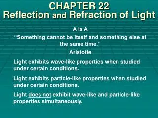
The spectrum includes more than visible light • Not all energy is visible to the human eye. • There are a variety of radiation forms – including X-rays, microwaves and radio waves. • These are all examples of electromagnetic waves. • Light has been described as a particle, a wave and a combination of the two. • We will focus on the wave-like properties of light for this chapter. Color blind chart
Electromagnetic waves vary depending on frequency and wavelength • Light is considered to be a wave composed of oscillating electric and magnetic fields. • Therefore, electromagnetic waves are transverse waves of electric and magnetic fields at right angles. • These waves are distinguished by their different wavelengths and frequencies. • In visible light, wavelength and frequency account for the different colors. Electromagnetic Waves
All electromagnetic waves move at the speed of light • All forms of electromagnetic radiation travel at a single high speed in a vacuum. • For calculations in this book, the value of “c” is 3.00 x 10⁸ m/s
Practice AElectromagnetic Waves • The AM radio band starts at 5.4 x 10⁵ Hz. • What is the wavelength of this frequency? ƒ = 5.4 x 10⁵ Hz c = 3.00 x 10⁸ m/s λ = ? c =ƒ λ answer 560 m
Waves can be approximated as rays • The broad crest of the wave that appears perpendicular to a water wave’s motion consists of a line of water particles. • In any type of wave, these lines of particles are called wave fronts. • Treating this propagating wave as a straight line perpendicular to the wave front is called a ray.
Illuminance decreases as the square of the distance from the source • The intensity of light depends both on the amount emitted and the distance from the source. • The rate light is emitted from a source is called “luminous flux” and is measured in lumens. • Brightness decreases by the square of the distance from the source. • Imagine how dim each square would become the father away from the source you are.
Questions1. Radiation forms like X-rays, microwaves, radio waves are all examples of ______________ waves.2. Electromagnetic waves are transverse / longitudinal waves of electric and magnetic fields at right angles.3. In visible light, wavelength and frequency account for the different ______.4. T / F All forms of electromagnetic radiation travel at a single high speed in a vacuum.5. Brightness decreases by the _______ of the distance from the source. electromagnetic ___________ colors true square
13.2 Flat Mirrors Reflection of Light • Light traveling through any uniform substance like air, water, a vacuum, always travels in a straight line. • If the substance changes, the path of the light will be different. • When light strikes a wooden table, part of the light is absorbed and some is deflected. • The change in direction of light is called reflection. • Even the best mirrors can only reflect 90% of their light.
The texture of a surface affects how it reflects light • Light that is reflected from a rough, textured surface, like paper or fabric, is reflected in many directions. • This is known as diffuse reflection. • Light reflected from shiny surfaces, like a mirror or calm water, is reflected in one direction only. • This is known as specular reflection.
Incoming and reflecting angles are equal • There is a similarity between incoming and reflected light rays. • The incoming light makes the angle of incidence and the reflected light makes the angle of reflection. • These angles will be θ = θ’ respectively. • A line perpendicular to the reflecting surface is known as the normal. angle of incidence
Flat Mirrors • The simplest type of mirror is the flat mirror. • When viewing an object in a mirror, we refer to its distance from the mirror as the object distance. • For this distance we use the p symbol. • What we see behind the mirror, or reflected image, we use the q symbol for image distance. • Flat mirrors always produce an image in the mirror. This is known as a virtual image.
Image location can be predicted with ray diagrams • This ray diagram uses simple geometry to locate an image formed by a mirror. • The object distance (p) and image distance (q) are shown proportional to their actual size. • To draw a ray image, start with the top of the object and draw a line perpendicular to the mirror’s surface. • Next, draw a ray at an angle so it reflects off the mirror as shown. • Third, use a dotted line to follow the reflected ray behind the mirror to show where the top of the virtual image would be. p = q Virtual image
Ray tracing procedure will work for any object placed in front of a flat mirror. • The image formed by a flat mirror appears reversed to an observer in front of the mirror. • Note how this writing is reversed.
Questions1. The change in direction of light is called ________.2. Light that is reflected from a rough, textured surface, like paper or fabric, is reflected in many directions, this is known as _______ reflection.3. The incoming light makes the angle of _________ and the reflected light makes the angle of reflection.4. When viewing an object in a mirror, we refer to its distance from the mirror as the ______ distance.5. The image formed by a flat mirror appears ________ to an observer in front of the mirror. reflection diffuse incidence object reversed
13.3 Curved Mirrors Concave Spherical Mirrors • These special mirrors can form images that are larger than normal when the object is close, see (a). • When the object is farther away, the image becomes smaller and upside down. • (a) below is a virtual image like flat mirror produce. • (b) is a real image and can be projected.
Concave mirrors can be used to form real images • Concave mirrors are like the inside of a sphere. • We can determine where images will form by knowing their radius of curvature, “R” measured from the back of the mirror. • And their center of curvature, located at (C).
Imagine a light bulb placed upright at a distance p from a concave spherical mirror, as shown here. • The base of the bulb sits on a center line known as the principal axis. • The light rays from the bulb diverge from the bulb and reflect through the image point. • Here the image will form in front of the mirror, making a real image. Note the bulb projected on the glass.
Image created by spherical mirrors suffer from spherical aberration • Not all rays intersect at the image point. • For rays that are far from the principle axis and mirrors with small radius of curvature, this is common. • This creates a condition known as spherical aberration. • In the next examples, we will only use rays near the principal axis called paraxial rays.
Image location can be predicted with the mirror equation • If the object distance and radius are known, you can predict where the image will appear. • This equation relates object distance, p, image distance q, and the radius of curvature, R. • Light striking the mirror almost parallel reflects and converges in a location known as the focal point. • The focal point is always half the length of the radius of curvature.
Since the focus is always half the radius of curvature our equation can be expressed in terms of focal length. • The region where light rays reflect and form real images is called the front side of the mirror. These are positive values and given a positive sign (+). • The other side, where they do not exist, is called the back side of the mirror. These are negative (-) images. • Objects and images above the principal axis are (+) when above and (-) when they are below.
Magnification relates image and object sizes • Curved mirrors can change the size of the image, this is known as magnification. • The magnification, M, is the ratio of image height to object height. • If the image is smaller than the object, its magnification is less than one. If it is larger, greater than one.
For images in front of a mirror, M is negative and the image is upside down (inverted). • When behind the mirror, M is positive and the image is upright. • This table shows the type of image, its orientation and if M is +/-
Ray diagrams can be used for concave spherical mirrors • When drawing a ray diagram for concave mirrors, you follow similar steps as that for flat mirrors. • However, with concave mirrors, you include the center of curvature and focal point. • Below are the rules for drawing reference rays. Concave mirror
Concave mirrors can produce both real and virtual images • This example shows that if the object is far from the mirror, the light rays converge at the focal point (F) and create an image there.
When the object is outside the center of curvature we see an image that forms between C and F. • The image is real, inverted and smaller that the object.
When our object is right at C, a real inverted image is produced. • This time with an equal magnification.
When our object is between C and F, we get a real inverted image with a magnification greater than 1.
Only when our object is between F and the mirror do we get a virtual image. • In this example our image has a magnification greater than 1. Concave image changes
Practice BImaging with Concave Mirrors • A concave spherical mirror has a focal length of 10.0 cm. • Locate the image of a pencil that is placed upright 30.0 cm from the mirror, q = ?. • Find the magnification of the image, M = ?.
Answer Q = 15 cm, M = -0.50
Convex Spherical Mirrors • You may not have noticed the words on a car’s side mirror. • “Objects in mirror are closer than they appear” • It says this because this type of mirror is a convex spherical mirror that bulges outward from its center. • This type of mirror is called a diverging mirror because the incoming rays diverge after reflection.
Convex mirrors always produce virtual images. • The image distance is always negative because the mirrored surface is opposite the radius of curvature. • This makes the focal length negative as well. • This table summarizes the sign conventions between convex and concave mirrors.
Because the focal point and center of curvature are located behind the mirror, we will use dotted lines in our ray diagrams. • This always gives us a virtual, upright image that has a magnification less than 1. Convex ray diagram
Convex mirrors take objects in a large field of view and produce smaller images. • They help an observer get a better view of a large area all at once. • You sometimes see them in intersections, stores, hallways and as side mirrors on cars.
Practice CConvex Mirrors • An upright pencil is placed in front of a convex spherical mirror with a focal length of 8.00 cm. • An upright image of 2.50 cm tall is formed 4.44 cm behind the mirror. • Find the position of the object, the magnification of the image and the height of the pencil.
First we solve for object distance (p). answer • Now for magnification… answer • Object height… answer 10.0 cm 0.444 5.63 cm
Parabolic Mirrors • Certain rays in diagrams do not intersect exactly at the image point, see below. • This is especially true for rays far from the principle axis. • Rays that reflect at points on the mirror far from the principal axis converge at slightly different points. • This produces a blurred image, an effect known as spherical aberration.
Parabolic mirrors eliminate spherical aberration • The simplest way to reduce the effect of spherical aberration is to use a small mirror. • However, very large mirrors are used in astronomical telescopes. • They reduce the effects of spherical aberration by using parabolic mirrors. • These are curved in such a way as to focus all rays on the focus. • The opposite can be done projecting light rays in flashlights and car headlight mirrors.
Reflecting telescopes use parabolic mirrors • All electromagnetic radiation obeys the laws of reflection. • Radio telescopes can use parabolic reflectors to focus incoming energy from space. • There are two types of telescopes, one that uses lenses and ones that use mirrors. • These are called reflecting telescopes. • As shown here they reflect the incoming light onto a small reflector mirror and magnify the image. Telescope
Questions1. T / F A real image can be projected.2. The focal point is always ____ the length of the radius of curvature.3. Curved mirrors can change the size of the image, this is known as ____________.4. T / F When our object is at F, no image forms!5. Convex mirrors always produce ______ images.6. Convex mirrors take objects in a large field of view and produce (smaller / larger) images. true half magnification true virtual ______
13.4 Color and Polarization Color • Color of an object can appear different under certain lighting conditions. • Objects absorb certain wavelengths from light striking them and reflect the rest. • The color of an object depends on which wavelengths of light shine on the object and which wavelengths are reflected. • If all the wavelengths are reflected, the object is white. • If all the wavelengths are absorbed, the object is black.
Additive primary colors produce white light when combined • White light can be dispersed into its elementary colors. • This can be seen using a prism. • Elementary colors can be combined to form white light. • This can also be done by shining light through red, green and blue filters. • These three colors are additive primary colors and together produce white light again.
Other colors are produced by combining (overlapping) red and green to make yellow. • Because yellow is opposite blue here it is called a complementary color of blue. • Televisions use the additive colors of RGB to form luminous dots or pixels when they are struck by electrons. • Varying the brightness and combinations of these colors produce the limitless colors and shades we see. • Humans see color because we have special cone cells in our eyes that are sensitive to the RGB wavelengths. Colors
Subtractive primary colors filter out all light when combined • When working with a substance like paint, it absorbs light. • When blue and yellow are mixed, we get green. • If you are looking at just the color blue, it is because all the other colors are absorbed while blue is the only one reflected. • The primary pigments of subtractive colors are cyan, magenta and yellow. • All of these colors mixed together form black. Subtractive