Download
1 / 26
310 likes | 385 Views
AUTOMATIC METER READING SYSTEMS. S.E. ELECTRICAL By Rajeev Bapat Mohit Atale Nitin Sapale Yadavrao Tasgaonkar Institute of Engineering & Technology Chandhai, Bhivpuri Road Station, Tal. Karjat, Dist. Raigad. Definition. AMR

E N D
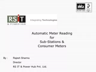
AUTOMATIC METER READING SYSTEMS S.E. ELECTRICAL By Rajeev Bapat Mohit Atale Nitin Sapale Yadavrao Tasgaonkar Institute of Engineering & Technology Chandhai, Bhivpuri Road Station, Tal. Karjat, Dist. Raigad
Definition • AMR • Automatic Remote Meter Reading . • Automating the process of measurement through digital communication techniques.
ELECTRO-MECHANICAL • Low Accuracy • Control – NIL • Communications - Expensive • Theft Detection – Poor PAST • DIGITAL SOLID STATE • High Accuracy • Control – LIMITED • Communications – External through Retrofit • Theft Detection – Node only CURRENT • NEXT GEN SMART METER & IT SYSTEM • Very High Accuracy • Control – FULL • Communications – Built in (on chip / PCB) • Theft Detection – High (Network level) NEXTGEN METERING SYSTEM
Critical Benefits from AMRS • Ability to detect tamper events and outage occurrences. • Remotely Connect/ Disconnect power supply through meter. • Calculate transformer loading and sizing from interval data • 15 minute interval data gives accurate load information for supply scheduling, switching operations, planning etc • Monitor voltage at each premise to know conditions when to operate capacitor switches or regulators • Consistent and granular data for improved accuracy
How AMR works ? • Remotely reads customer meters and then transfers the data into the billing system • Reduce the need for meter readers to manually gather utility meter readings each month.
PRIMARY COMPONENTS: • Meter Interface Module • Communication System • Central Office Equipment
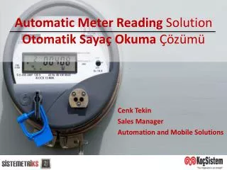
Meter interface module • The AMR system starts at the meter. Some means of translating readings from rotating meter dials, or cyclometer style meter dials, into digital form is necessary in order to send digital metering data from the customer site to a central point. • Electro - optical interface • Signal Processing Electronics • RAM & Program Memory
Retrofit Card • Consists of a single PCB, which converts CF pulses of Electronic Energy Meters to Electrical pulses, accumulate them and generate a meter reading with help of Microprocessor. • Microprocessor converts this data into Power Line Modulation. • Existing Meter Reading, Meter Constant and Meter ID is stored in NV RAM of Micro controller, before Retrofit is made operational. • One unit is incremented when Retrofit senses the pulses equal to Meter constant. • The incremented unit are stored in the NV RAM of the Micro controller.
Communications systems Used for the transmission, or telemetry, of data and control send signals between the meter interface units and the central office. 1. GSM Based Communication Single stage communication between Meter and central station through GSM Modem 2. PLCC Based Communication Single stage communication between Meter and central station through electricity network
GSM Based Communication • GSM modem • Antenna
GSM Modem • Dual Band or Triband GSM GPRS modem (EGSM 900/1800MHz) / (EGSM 900/1800 / 1900 MHz ) • Designed for GPRS, data, fax, SMS and voice applications • Fully compliant with ETSI GSM Phase 2+ specifications (Normal MS) • Interfaces • RS-232 through D-TYPE 9 pin connector • Power supply through Molex 4 pin connector • SMA antenna connector • Toggle spring SIM holder • Red LED Power on • Green LED status of GSM / GPRS module
GSM Network In AMR • Utilizing an existing cellular network for data transportation requires no additional equipment or software, resulting in a significant savings in both time and capital. • Cellular technology utilizes an encryption technique to prevent an outside source from receiving the transmitted data. • The cellular network provides full two-way communications, allowing scheduled reads, demand reads, alarm and event reporting, power outage reporting and power restoration reporting.
Data Concentrator Unit (DCU) • The Data Concentrator sits on the loop of secondary of the distribution transformer.Collects meter readings from all the meters using Power Line Communication System at predefined intervals. • The DCU and all the meters connected to it can be considered as a sub-system of the HCS. The sub-system is set up with a DCU monitoring the low voltage power zone downstream of a Distribution Transformer.
Power Line Carrier Communications • Most economically viable technology for transferring Meter data to DCU. • Uses the technique of communicating the data over existing Electrical Lines which carry LT power to the site. • Employs an ASIC, which accepts digital data & converts it into FSK modulation and transmits it over the power line by sensing a zero crossing of 220V sine wave. • Typical frequency used for frequency modulation is 132KHz.
Central office systems • Central office systems equipment includes: • Modems • Central server • Client Software for data acquisition and data analysis
Selection Of Communication • PLCC Best Suited for LT 440 V network for detecting outages, tamper events and performing remote disconnect • Uses same power lines as communication media, so ideally suited for rural/ agricultural connections • Communication on HT side can be implemented via a choice of GSM, CDMA, RF or PSTN
Meter Data Analysis & Energy Accounting Metering Billing Operations Customer Service • Network Schematic Modelling:Modelling the physical network structure (substation, HT Feeder, Transformer, LT Feeder) & keeping it updated as changes occur. • Handle Feeder Switching scenarios for Energy Accounting: • From One LT feeder to another on the same transformer • From One distribution Transformer to another distribution transformer, but with the same LT feeder • From One HT feeder to another HT feeder but through the same DT and LT feeder
- contd. • Reports/Analysis • Identifying customers with tampered meters or zero readings. • Monitoring the energy consumed /supplied and energy accounts /reconciliation over a particular duration • by customer category • by network device (LT Feeder, transformer, HT Feeder, Substation) • by geographical area (zone, circle, division, subdivision) • Monitoring the maximum demand, voltage levels, current, power consumption/ load on each meter. • Can calculate Max demand of LT / HT feeder, Transformer & Substation • Abnormal consumption report • Ability to build ad-hoc reports without having to know any programming language or query language. • Energy Balance Report • Areas of High Loss Report • Consumption trends Report
Advantages Of AMR System ELECTRIC COMPANY BENEFITS
CUSTOMER BENEFITS · Precise consumption information · Clear and accurate billing · Automatic outage information and faster recovery · Better and faster customer service · Flag potential high consumption before customer gets a high bill.