Download
1 / 23
230 likes | 236 Views
Device simulation of CMOS Pixel Sensors with synopsys. Andrei Dorokhov PICSEL group, IPHC Ecole " Simulation de détecteurs " 2014 LPNHE, Paris, 15-17 Septembre 2014. Contents. CMOS Pixel Sensors (CPS) Simulation with TCAD Simulation examples for CPS. CMOS Pixel Sensors.

E N D
Device simulation of CMOS Pixel Sensors with synopsys Andrei Dorokhov PICSEL group, IPHC Ecole " Simulation de détecteurs " 2014 LPNHE, Paris, 15-17 Septembre 2014
Contents • CMOS Pixel Sensors (CPS) • Simulation withTCAD • Simulation examples for CPS Andrei.Dorokhov@ires.in2p3.fr
CMOS Pixel Sensors Readout electronics between Nwells P-type epitaxial layer Nwell • CPS (also known as Monolithic Active Pixel Sensors (MAPS)) are devices for charged particle or light detection • sensor and electronics are implemented in the standard CMOS substrate • electronics can perform the following tasks: • Correlated double sampling • Digitization • Discrimination • Zero suppression • ….. • Storage e-h particle Andrei.Dorokhov@ires.in2p3.fr
CMOS Pixel Sensors • CPS are under development by Strasbourg group since 1999 • Many different prototypes (Mimosa**) have been optimized for: • noise and signal-to-noise ratio • charge collection efficiency for visible light and charged particles detection • power consumption • signal processing (discriminators, ADCs, zero suppression or compression logic) • radiation tolerance • speed • reliability Andrei.Dorokhov@ires.in2p3.fr
CPS: principle of operation • energy of a particle transferred to creation of e-h pairs in silicon bulk (p-type epitaxial layer) • moving electrons and holes induce current on sensing electrodes (Nwells) • the current is converted to voltage on Nwell/Pepi diode capacitance • physics processes describing the charge collection are very complex • device simulation is needed to understand them and to verify new ideas… Andrei.Dorokhov@ires.in2p3.fr
Contents • CMOS Pixel Sensors (CPS) • Simulation withTCAD • Simulation examples for MAPS Andrei.Dorokhov@ires.in2p3.fr
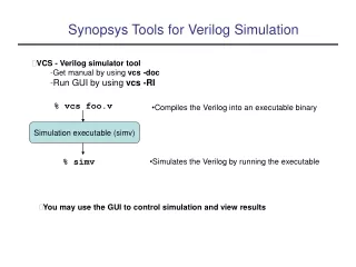
Simulation with Sentaurus TCAD from Synopsys • basic properties: • electric field • potentials • leakage current • capacitance • transient response on particle: • charge collection • collection time device simulation: fabricated device parameters - doping concentration, geometry, applied voltages, tracks of elementary particles process simulation: temperature, pressure, velocity,.... used by FABs in order to improve fabrication of CMOS devices, the process parameters are unknown to us... Andrei.Dorokhov@ires.in2p3.fr
Prepare for simulation: defining of doping profiles • mesh generator: " mesh" in Sentaurus • two input files: boundary and doping Example of doping definition file: Title "Pixel" Definitions { Constant "substrate" { Species = "BoronActiveConcentration" Value = 1e13 } AnalyticalProfile "NW" { Species = "PhosphorusActiveConcentration" Function = Erf(SymPos = 1, MaxVal = 1.0e+17, ValueAtDepth = 1e+13, Depth = 1.1) LateralFunction = Gauss(Length = 0.02) } } Placements { Constant "substrate" { Reference = "substrate" EvaluateWindow { Element = cuboid [(0, 0, 0) (12, 40, 40)] } } AnalyticalProfile "diode_0_0" { Reference = "NW" ReferenceElement { Element = rectangle [(12, 8.345, 8.345) (12, 11.655, 11.655)] Direction = negative } } } Example of 3D boundary file: Silicon "substrate" { cuboid [(0 0 0), (12 40 40)] } Contact "pixel_0_0" { rectangle [(12, 9.345, 9.345) (12, 10.655, 10.655)] } Contact "backplane_contact" { rectangle [(0, 1, 1) (0, 39, 39)] } Andrei.Dorokhov@ires.in2p3.fr
Prepare for simulation: device simulation • simulator: "dessis" in Sentaurus • one input file: commands for simulation Example of command file: Physics { Temperature = 293.15 Mobility( DopingDep HighFieldsat Enormal ) Recombination( SRH(tunneling(Hurkx)) Auger surfaceSRH Radiative TrapAssistetAuger ) HeavyIon ("mip0") ( PicoCoulomb Gaussian time=1.0e-9 direction=(1,0,0) location=(0,36.6667,7.77778) wt_hi = 3 length= 1000 let_f = 1e-5 ) } ...... Electrode { { Name="backplane_contact" Voltage=0.0 } { Name="pixel_0_0" Voltage=1.8 } } ..... Solve { Coupled { Poisson Electron Hole Contact} Transient ( InitialTime=0.0 FinalTime=300.0e-9 InitialStep=0.1e-9 MinStep=1e-18 MaxStep=10.0e-9 Increment=1.2 ) { Coupled { Poisson Electron Hole Contact} Plot ( Time= ( 0; 1e-9; 1.2e-9; 1.5e-9; 2e-9; 5e-9; 10e-9; 20e-9; 50e-9; 150e-9; 300e-9 ) NoOverwrite ) } } Declare which models will be used for simulation Define particle track: HeavyIon or AlphaParticle models are available, however one can redefine model parameter values in order to incorporate other particles (m.i.p. in example) Set electrodes potentials (possible also current or charge) Poisson and continuity equations : the currents on electrodes are known Solve equations and plot them at several time points Andrei.Dorokhov@ires.in2p3.fr
Defining tracks of particles : multiple particles Heavy Ion is used to simulate m.i.p: parameters of energy deposition in silicon can be modified from default values in "dessis.par" file: HeavyIon { * Generation by a Heavy Ion : * The temporal distribution is a Gaussian Function * The radial spatial distrbution can be a exponential, a gaussian function or give by table * The spatial distribution along the path is coming from a table * G = LET(l)*R(r)*T(t) * LET(l) = a1 + a2*l + a3 exp(a4*l) + k'*[c1*(c2 + c3*l)^(c4) + Lf(l)] * with Lf(l) = { Lf1, Lf2, Lf3, ...} * Lfi are the Lf values for each length lengthi * if Radial_Exponential_Distribution; * R(r) = exp[-(r/wt)] * case 3D (unit pC/um) : k' = k / (2*pi*wt^2) * case 2D (unit pC/um) : k' = k / (2*e*wt) * if unit = Pairs/cm^3 => k' = k * if Radial_Gaussian_Distribution; * R(r)= exp[-0.5*(r/wt)^2] * case 3D (unit pC/um) : k' = k / (pi*wt^2)) * case 2D (unit pC/um) : k' = k / (e*wt*Sqrt(pi)) * if unit = Pairs/cm^3 => k' = k * with wt(l) = { wt1, wt2, wt3 ...} * wti are the wt values for each length lengthi * e = 1 um s_hi = 100.0000e-12 # [s] default is 2.0e-12 # * See the manual for more details. } HeavyIon ("mip0") { s_hi = 100.0000e-12 } HeavyIon ("mip1") { s_hi = 100.0000e-12 } HeavyIon ("mip2") { s_hi = 100.0000e-12 } HeavyIon ("mip3") { s_hi = 100.0000e-12 } ... ... one track Andrei.Dorokhov@ires.in2p3.fr
Visualization of the results of simulation : DC solution • visualization with: "svisual" in Sentaurus DC solution is presented: electrostatic potential Different zones can be displayed, for example the most important depletion zone (white color) Andrei.Dorokhov@ires.in2p3.fr
Charge transport : transient response current (charge = 2.4e-15 ) current ( charge = 3.6e-15) particles come at this moment in average 67 % of total deposited by m.i.p. charge is collected, also one can find the typical charge collection time (<10 ns) Andrei.Dorokhov@ires.in2p3.fr
Charge transport in CPS: visualization of charge in TCAD is not possible to track charge created by the m.i.p, but excess of electron density can show the presence of charge created by the particle The snapshots of electron density can be saved along the simulation, so one can see how the excess of charge evacuated bu the charge collections electrodes Andrei.Dorokhov@ires.in2p3.fr
Contents • CMOS Pixel Sensors (CPS) • Simulation withTCAD • Simulation examples for CPS Andrei.Dorokhov@ires.in2p3.fr
Example 1: Simulation of charge sharing Distance between particle impact point and center of (3,3) pixel in 5x5 matrix * Chip: Mimosa 5, developed at IPHC, Strasbourg ** Measurements with laser: at IPNL, Lyon Andrei.Dorokhov@ires.in2p3.fr
P-type epitaxial layer thickness Example 2: Geometry influence on charge collection efficiency Nwell size • Optimisation for 14um: • C2,4 =3 fF, C4,5 = 6 fF • ENC4,5/ENC2,4 ~ 2 • signal ~ charge collection [%] : S4,5/S2,4 ~ 3 • (S/N)4,5/(S/N)2,4= 3/2 Pitch size S/N higher with 4.5um Particle impact position uniformly distributed over the pitch area, results are averaged Measurements of Mimosa 16 developed at IPHC and IRFU, 20 um epi - 2.4 um Nwell: CCE 3x3 ~ 23% 4.5 um Nwell: CCE 3x3 ~ 52% Andrei.Dorokhov@ires.in2p3.fr
Example 3: epi doping influence on charge collection efficiency P-type epitaxial layer Uniform doping Nwell Graded doping Pwell Andrei.Dorokhov@ires.in2p3.fr
Example 3 :epi doping influence on charge collection efficiency Excess of electrons from particle will be there Andrei.Dorokhov@ires.in2p3.fr
Example 3: epi doping influence on charge collection efficiency and collection time epi p-type doping concentration, cm-3 Pixel pitch 20 um2 Nwell 4 um2 Distance from Nwell surface towards the bulk, um Andrei.Dorokhov@ires.in2p3.fr
Example 4: epi doping influence on depletion For comparison: standard CMOS technology, low resistivity P-epi high resistivity P-epi: size of depletion zone size is comparable to the P-epi thickness-> show about x2 charge collected in seed, used in upgrade of STAR HFT detector Andrei.Dorokhov@ires.in2p3.fr
Example 5: charge collection vs position of track signal spectrum from pixel • simulated charge vs particle position in a 3x3 pixels of pitch 20um matrix selected amplitudes of seed pixel positions only • interpolated results from simulation: charge vs distance between particle and central pixel measuredsignal spectrum from pixel: visible excess of events is not seen in simulation-> suspect saturation of discharge time in the front-end amplifier Andrei.Dorokhov@ires.in2p3.fr
Contents • CMOS Pixel Sensors (CPS) • Simulation withTCAD • Simulation examples for CPS Andrei.Dorokhov@ires.in2p3.fr
Outlook • the following properties of semiconductor detectors can be extracted from simulation with TCAD: • Charge collection efficiency • Collection time • Charge sharing • Capacitance • Electric field • Leakage current • the simulations can be used: • for estimation of detector performance • optimization of front end electronics • verification of new ideas • complementary to measurements study Andrei.Dorokhov@ires.in2p3.fr