Download
1 / 61
610 likes | 699 Views
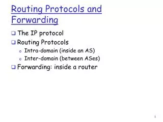
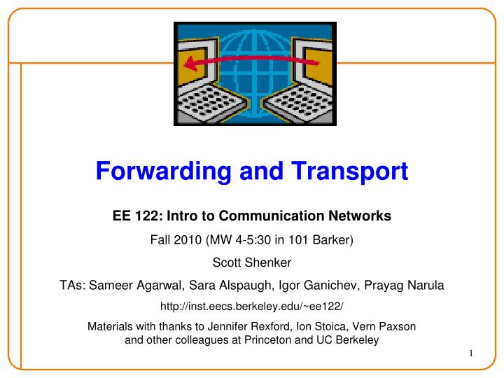
Forwarding and Transport. EE 122: Intro to Communication Networks Fall 2010 (MW 4-5:30 in 101 Barker) Scott Shenker TAs: Sameer Agarwal, Sara Alspaugh, Igor Ganichev, Prayag Narula http://inst.eecs.berkeley.edu/~ee122/

E N D
Forwarding and Transport EE 122: Intro to Communication Networks Fall 2010 (MW 4-5:30 in 101 Barker) Scott Shenker TAs: Sameer Agarwal, Sara Alspaugh, Igor Ganichev, Prayag Narula http://inst.eecs.berkeley.edu/~ee122/ Materials with thanks to Jennifer Rexford, Ion Stoica, Vern Paxsonand other colleagues at Princeton and UC Berkeley
Announcements • HW #1 Being graded • HW #2 Out tonight • I have 61 slides….. • If I finish them, you all flunk.
Goals of Today’s Lecture • Quick summary of IP addressing • IP packet forwarding • Transport layer • Reliable delivery • Non-goals: • Details of TCP (later) • Congestion control (later) • Finishing these slides….
Summary of IP Addressing • 32-bit numbers identify interfaces • Allocated in prefixes • Non-uniform hierarchy for scalability and flexibility • Routing is based on CIDR • A number of special-purpose blocks reserved • Address allocation: • ICANN RIR ISP customer network host • Issues to be covered later • How hosts get their addresses (DHCP) • How to map from an IP address to a link address (ARP)
CIDR: Hierarchal Address Allocation • Prefixes are key to Internet scalability • Addresses allocated in contiguous chunks (prefixes) • Routing protocols and packet forwarding based on prefixes 12.0.0.0/15 : : : 12.2.0.0/16 12.3.0.0/22 12.3.0.0/16 12.3.4.0/24 : : : : 12.0.0.0/8 12.3.254.0/23 12.253.0.0/19 12.253.32.0/19 12.253.64.0/19 12.253.0.0/16 12.253.64.108/30 : 12.253.96.0/18 12.253.128.0/17
Hierarchical Structure • Helps scalability • But also allows for easy delegation of control • ICANN RIR ISP customer network host • This is a recurring Internet theme (e.g., DNS next lecture) • Deployability and scalability arise from loose hierarchical structure
But What Are Addresses Used For? • They allow the network to deliver packets to the right destination • They are a means to achieve a goal • Not a goal themselves • This is done by hop-by-hop packet forwarding • To which we now turn…..
Hop-by-Hop Packet Forwarding • Each router has a forwarding table • Maps destination addresses… • … to outgoing interfaces (= links) • Forwarding table derived from: • Routing algorithms • (or static configuration) • Upon receiving a packet • Inspect the destination IP address in the header • Index into the forwarding table • Forward packet out appropriate interface
Using the Forwarding Table • With classful addressing, this is easy: • Early bits in address specify mask • Class A [0]: /8 Class B [10]: /16 Class C [110]: /24 • Can find exact match in forwarding table • Use prefix as index into hash table • Why won’t this work for CIDR? • Address doesn’t specify mask • Two problems with CIDR forwarding tables • Finding match isn’t trivial • Non-topological addressing
Example #1: Provider w/ 4 Customers Link 1 Link 4 Link 2 Link 3 Provider 201.143.0.0/22 201.143.4.0/24 201.143.5.0/24 201.143.6.0/23
11001001 11001001 11001001 11001001 10001111 10001111 10001111 10001111 0000011− 00000100 00000101 000000−− −−−−−−− −−−−−−− −−−−−−− −−−−−−− Finding the Match • No address matches more than one prefix • But can’t easily find match • Consider 11001001100011110000010111010010 • First 21 bits match 4 partial prefixes • First 22 bits match 3 partial prefixes • First 23 bits match 2 partial prefixes • First 24 bits match exactly one full prefix 201.143.0.0/22 201.143.4.0/24 201.143.5.0/24 201.143.6.0/23
Example #2: Aggregating Customers 201.144.0.0/21 201.143.0.0/21 Provider 2 Provider 1 201.144.0.0/22 201.143.0.0/22 201.144.4.0/24 201.143.4.0/24 201.143.5.0/24 201.144.5.0/24 201.143.6.0/23 201.144.6.0/23
Example #3: Complications Forwarding table more complicated when addressing is non-topological 201.144.0.0/21 201.143.0.0/21 Provider 2 Provider 1 201.144.0.0/22 201.143.0.0/22 201.144.4.0/24 201.143.4.0/24 201.143.5.0/24 201.144.5.0/24 201.143.6.0/23 201.144.6.0/23
11001001 11001001 11001001 11001001 11001001 11001001 11001001 11001001 10010000 10010000 10001111 10001111 10010000 10001111 10001111 10010000 00000100 0000011− 000000−− 00000101 00000100 00000101 000000−− 0000011− −−−−−−− −−−−−−− −−−−−−− −−−−−−− −−−−−−− −−−−−−− −−−−−−− −−−−−−− Unique prefix matching Provider 1 Provider 2
More compact representation Use /21s for bulk of traffic List /24s as exceptions 201.144.0.0/21 201.143.0.0/21 Provider 2 Provider 1 201.144.0.0/22 201.143.0.0/22 201.144.4.0/24 201.143.4.0/24 201.143.5.0/24 201.144.5.0/24 201.143.6.0/23 201.144.6.0/23
11001001 11001001 11001001 11001001 10001111 10001111 10010000 10010000 00000−−− 00000−−− 00000101 00000100 −−−−−−− −−−−−−− −−−−−−− −−−−−−− Arriving packet: 11001001 10010000 00000100 01101101 Arriving packet:11001001 10010000 00000101 01101101 Longest Prefix Match Provider 1 201.143.0.0/21 201.144.4.0/24 Provider 2 201.144.0.0/21 201.143.5.0/24
Why use longest prefix match? • Nontrivial to find matches in CIDR even w/o LPM • Because can’t tell where network address ends • Must walk down bit-by-bit • LPM decreases size of routing table • Speeding up lookup • Reducing memory consumption • But how does LPM work? • And how can we speed it up?
destination 201.10.7.17 Longest-Prefix-Match Forwarding Forwarding Table outgoing link prefix 201: 1100100110: 00001010 7: 00000111 17: 00010001 192: 11000000
destination 201.10.7.17 Longest-Prefix-Match Forwarding Forwarding Table outgoing link prefix 201: 1100100110: 00001010 7: 00000111 17: 00010001 192: 11000000
destination 201.10.7.17 Longest-Prefix-Match Forwarding Forwarding Table outgoing link prefix 201: 1100100110: 00001010 7: 00000111 17: 00010001 4: 0000010083: 01010011 128: 10000000
destination 201.10.7.17 Longest-Prefix-Match Forwarding Forwarding Table outgoing link prefix 201: 1100100110: 00001010 7: 00000111 17: 00010001 201: 11001001 10: 00001010 0: 00000000
destination 201.10.7.17 Longest-Prefix-Match Forwarding Forwarding Table outgoing link prefix 201: 1100100110: 00001010 7: 00000111 17: 00010001 201: 11001001 10: 00001010 6: 00000110
Longest-Prefix-Match Forwarding • Algorithmic problem: how do we do this fast? Forwarding Table outgoing link prefix destination 201.10.7.17 201: 1100100110: 00001010 7: 00000111 17: 00010001 2
Simple Algorithms Are Too Slow • Scan the forwarding table one entry at a time • See if the destination matches the prefix • Keep track of the entry with longest-matching prefix • If no match, use default route • Overhead is linear in size of the forwarding table • Today, that means 200,000-250,000 entries! • And, the router may have just a few nanoseconds • … before the next packet arrives • Need greater efficiency to keep up with line speed • Better algorithms • Hardware implementations
0 1 0 0 1 0* 0 1 00* 11* 100* 101* Patricia Tree • Store the prefixes as a tree • One bit for each level of the tree • Some nodes correspond to valid prefixes • When a packet arrives • Traverse the tree based on the destination address • Running time: scales with # bits in prefix
How Does Sending End Host Forward? • No need to run a routing protocol • Packets to the host itself (e.g., 1.2.3.4/32) • Delivered locally • Packets to other hosts on the LAN(e.g., 1.2.3.0/25) • Sent out the interface with LAN address (ARP) • Can tell they’re local using subnet mask(e.g., 255.255.255.128) • Packets to external hosts (any others) • Sent out interface to local gateway • I.e., IP router on the LAN • How this information is learned • Static setting of address, subnet mask, and gateway • Or: Dynamic Host Configuration Protocol (DHCP)
What About Reaching the End Hosts? • How does the last router reach the destination? • Each interface has a persistent, global identifier • MAC address (Media Access Control) - Layer 2 • Programmed into NIC • Usually flat address structure (i.e., no hierarchy) • Constructing an address resolution table • Mapping MAC address to/from IP address • Address Resolution Protocol (ARP) 1.2.3.7 1.2.3.156 1.2.3.4 ... host host host LAN router
5 Minute Break Questions Before We Proceed?
Role of Transport Layer • Application layer • Communication for specific applications • E.g., HyperText Transfer Protocol (HTTP), File Transfer Protocol (FTP), Network News Transfer Protocol (NNTP) • Transport layer • Communication between processes (e.g., socket) • Relies on network layer; serves the application layer • E.g., TCP and UDP • Network layer • Logical communication between nodes • Hides details of the link technology • E.g., IP
application transport network data link physical application transport network data link physical network data link physical network data link physical network data link physical network data link physical network data link physical logical end-end transport Transport Protocols • Provide logical communication between application processes running on different hosts • Run on end hosts • Sender: breaks application messages into segments, and passes to network layer • Receiver: reassembles segments into messages, passes to application layer • Multiple transport protocol available to applications • Internet: TCP and UDP (mainly)
Internet Transport Protocols • Datagram messaging service (UDP) • No-frills extension of “best-effort” IP • Multiplexing/Demultiplexing among processes • Reliable, in-order delivery (TCP) • Connection set-up & tear-down • Discarding corrupted packets • Retransmission of lost packets • Flow control • Congestion control • Services not available • Delay and/or bandwidth guarantees • Sessions that survive change-of-IP-address
4-bit Header Length 8-bit Type of Service (TOS) 4-bit Version 16-bit Total Length (Bytes) 3-bit Flags 16-bit Identification 13-bit Fragment Offset 8-bit Time to Live (TTL) 8-bit Protocol 16-bit Header Checksum 32-bit Source IP Address 32-bit Destination IP Address Options (if any) Payload
4-bit Header Length 8-bit Type of Service (TOS) 4-bit Version 16-bit Total Length (Bytes) 3-bit Flags 16-bit Identification 13-bit Fragment Offset 8-bit Time to Live (TTL) 8-bit Protocol 16-bit Header Checksum 32-bit Source IP Address 32-bit Destination IP Address Options (if any) Payload
8-bit Type of Service (TOS) 5 4 16-bit Total Length (Bytes) 3-bit Flags 16-bit Identification 13-bit Fragment Offset 8-bit Time to Live (TTL) 8-bit Protocol 16-bit Header Checksum 32-bit Source IP Address 32-bit Destination IP Address Payload
8-bit Type of Service (TOS) 5 4 16-bit Total Length (Bytes) 3-bit Flags 16-bit Identification 13-bit Fragment Offset 8-bit Time to Live (TTL) 6 = TCP17 = UDP 16-bit Header Checksum 32-bit Source IP Address 32-bit Destination IP Address Payload
8-bit Type of Service (TOS) 5 4 16-bit Total Length (Bytes) 3-bit Flags 16-bit Identification 13-bit Fragment Offset 8-bit Time to Live (TTL) 6 = TCP17 = UDP 16-bit Header Checksum 32-bit Source IP Address 32-bit Destination IP Address 16-bit Source Port 16-bit Destination Port More transport header fields …. Payload
Host receives IP datagrams Each datagram has source and destination IP address, Each datagram carries one transport-layer segment Each segment has source and destination port number Host uses IP addresses and port numbers to direct the segment to appropriate socket Multiplexing and Demultiplexing 32 bits source port # dest port # other header fields application data (message) TCP/UDP segment format
Ports • Need to decide which application gets which packets • Solution: map each socket to a port • Client must know server’s port • Separate 16-bit port address space for UDP and TCP • (src_IP, src_port, dst_IP, dst_port) identifies TCP connection • What about UDP? • Well known ports (0-1023): everyone agrees which services run on these ports • e.g., ssh:22, http:80 • Ephemeral ports (most 1024-65535): given to clients • e.g. chat clients, p2p networks
Unreliable Message Delivery Service • Lightweight communication between processes • Avoid overhead and delays of ordered, reliable delivery • Send messages to and receive them from a socket • User Datagram Protocol (UDP; RFC 768 - 1980!) • IP plus port numbers to support (de)multiplexing • Optional error checking on the packet contents • (checksum field = 0 means “don’t verify checksum”) SRC port DST port checksum length DATA
Why Would Anyone Use UDP? • Finer control over what data is sent and when • As soon as an application process writes into the socket • … UDP will package the data and send the packet • No delay for connection establishment • UDP just blasts away without any formal preliminaries • … which avoids introducing any unnecessary delays • No connection state • No allocation of buffers, sequence #s, timers … • … making it easier to handle many active clients at once • Small packet header overhead • UDP header is only 8 bytes
“Address for bbc.co.uk?” “212.58.224.131” Popular Applications That Use UDP • Multimedia streaming • Retransmitting lost/corrupted packets often pointless - by the time the packet is retransmitted, it’s too late • E.g., telephone calls, video conferencing, gaming • Recent streaming protocols using TCP (and HTTP) • Simple query protocols like Domain Name System • Connection establishment overhead would double cost • Easier to have application retransmit if needed
Transmission Control Protocol (TCP) • Connection oriented • Explicit set-up and tear-down of TCP session • Stream-of-bytes service • Sends and receives a stream of bytes, not messages • Congestion control • Dynamic adaptation to network path’s capacity • Reliable, in-order delivery • TCP tries very hard to ensure byte stream (eventually) arrives intact • In the presence of corruption and loss • Flow control • Ensure that sender doesn’t overwhelm receiver
Reliable Delivery • How do we design for reliable delivery? • How do you converse on a noisy phone line? • Positive acknowledgment (“Ack”) • Explicit confirmation by receiver • TCP acknowledgments are cumulative (“I’ve received everything up through sequence #N”) • With an option for acknowledging individual segments (“SACK”) • Negative acknowledgment (“Nack”) • “I’m missing the following: …” • How might the receiver tell something’s missing?Can they always do this? • (Only used by TCP in implicit fashion - “fast retransmit”)
Reliable Delivery, con’t • Timeout • If haven’t heard anything from receiver, send again • Problem: for how long do you wait? • TCP uses function of estimated RTT • Problem: what if no Ack for retransmission? • TCP (and other schemes) employs exponential backoff • Double timer up to maximum - tapers off load during congestion • A very different approach to reliability: send redundant data • Cell phone analogy: “Meet me at 3PM - repeat 3PM” • Forward error correction • Recovers from lost data nearly immediately! • But: only can cope with a limited degree of loss • And: adds load to the network
TCP Support for Reliable Delivery • Sequence numbers • Used to detect missing data • ... and for putting the data back in order • Checksum • Used to detect corrupted data at the receiver • …leading the receiver to drop the packet • No error signal sent - recovery via normal retransmission • Retransmission • Sender retransmits lost or corrupted data • Timeout based on estimates of round-trip time (RTT) • Fast retransmit algorithm for rapid retransmission
Packet ACK Automatic Repeat reQuest (ARQ) • Automatic Repeat Request • Receiver sends acknowledgment (ACK) when it receives packet • Sender waits for ACK and times out if does not arrive within some time period • Simplest ARQ protocol • Stop and Wait • Send a packet, stop and wait until ACK arrives Sender Receiver Timeout Time
How Fast Can Stop-and-Wait Go? • Suppose we’re sending from UCB to New York: • Bandwidth = 1 Mbps (megabits/sec) • RTT = 100 msec • Maximum Transmission Unit (MTU) = 1500 B = 12,000 b • No other load on the path and no packet loss • What (approximately) is the fastest we can transmit using Stop-and-Wait? • How about if Bandwidth = 1 Gbps?