Download
1 / 7
70 likes | 330 Views
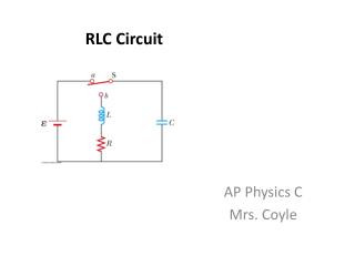
实验七 RLC 串联电路的幅频特性和谐振. 一、实验目的 l 、研究 RLC 串联电路的幅频特性(也就是谐振曲线) 2 、研究串联谐振现象及电路参数对谐振特性的影响。. 二、实验说明. 在 RLC 串联电路中,阻抗值是:. 三 实验内容. 测量幅频特性的实验电路如下,信号发生器输出正弦电压,频率可在 20 赫到 20 千赫范围内变化. 1 、测量 RLC 串联电路的幅频特性 I ( f ),并测出谐振频率 f 。

E N D
实验七 RLC串联电路的幅频特性和谐振 一、实验目的 l、研究RLC 串联电路的幅频特性(也就是谐振曲线) 2、研究串联谐振现象及电路参数对谐振特性的影响。
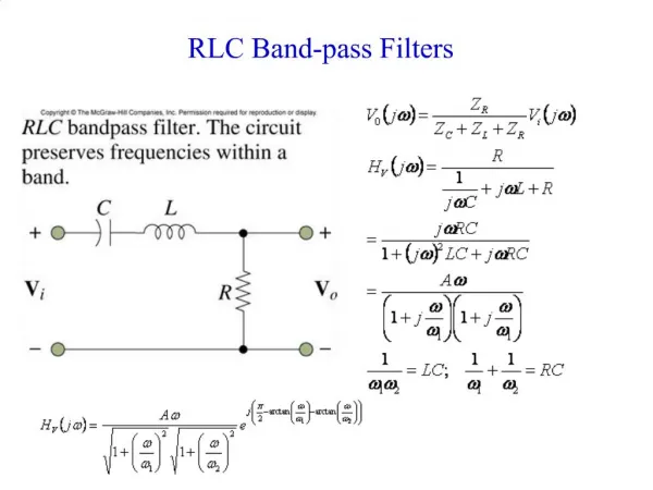
二、实验说明 • 在RLC串联电路中,阻抗值是:
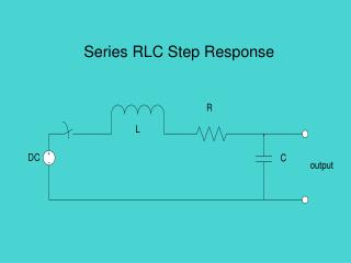
三 实验内容 测量幅频特性的实验电路如下,信号发生器输出正弦电压,频率可在20赫到20千赫范围内变化
1、测量RLC串联电路的幅频特性I(f),并测出谐振频率f。1、测量RLC串联电路的幅频特性I(f),并测出谐振频率f。 • 具体方法:采用电阻取样法测定回路电流,取样电阻采用Ro=10Ω。调整信号源频率,取样电阻两端接的交流毫伏表指示值最大时,调整信号源幅度,使Us=1V,重新调整频率使电流最大,此时f即为f0,电流为I0。Q2>Q1
2.改变电阻R=100Ω,重复1 3.改变L==200mH,重复1。计算值,并测定该值所对应的f值通频带Δf 4.Q值的测定, 用毫伏表测L(或C)上两端的谐振时的电压,此值即Q值;用数字万用表电阻档测L的直流也阻r(R0=R+r)带入上面的公式,看它们的Q值误差有多大。
四、实验报告要求 • 1、实验目的 • 2、原理简述 • 3、实验内容:含实验步骤、实验电路、表格、数据等 • 4、绘制幅频特性曲线。 • 5、Q值的相对误差分析。