Download
1 / 28
280 likes | 471 Views
LHC Accelerator Research Program bnl-fnal-lbnl-slac. Cryogenics for arc and transfer line magnets. Outline: LER cryogenic system design LHC cryogenics infrastructure at CERN LER arc magnet cryogenics Current leads for arc magnets LER transfer line magnet cryogenics

E N D
LHC Accelerator Research Program bnl-fnal-lbnl-slac Cryogenics for arc and transfer line magnets Outline: • LER cryogenic system design • LHC cryogenics infrastructure at CERN • LER arc magnet cryogenics • Current leads for arc magnets • LER transfer line magnet cryogenics • Current leads for fast switching magnets • Summary
LER cryogenic system design • For any cryogenic system design, first thing we need to know is to identify the heat load Q, conduction, radiation, Joule heating, etc. • Figure out at what temperature level T this heat load is introduced into the cryogenic system, 1.9 K, 4.5 K or 50 -75 K etc. • Then we need to know where these cryogenic cooling powers coming from and how much the temperature difference between the conductor and coolant at heat load Q and temperature T Thermal shield Cryostat m, THe Q, Ts Magnet
LHC cryogenic system layout • LER will use LHC existing cryogenic infrastructure as show below P5 P4 P6 • 5 cryogenic islands • 8 refrigerators • 2 at P4, 6 and 8 • 1 at P1.8 and P2 • 1 refrigerator serves 1 sector, 3,300 m • Each refrigerator is 18 kW @ 4.5K and 600 kW pre-cooler P3 P7 P2 P8 P1 P1.8
LHC helium refrigerator system setup HP MP LHC supply LP LHC return Shield supply Shield return 300 K 20 K 90 K 75 K 50 K 4.5 K
LHC cryogenic distribution line (QRL) Cryogenic Distribution Line (QRL)
Installed refrigeration capacity in the LHC sectors * The high-load sectors are 1-2, 4-5, 5-6 and 8-1. - The low-load sectors are 2-3, 3-4, 6-7 and 7-8.
Static heat in-leaks in distribution system Other means Interconnection boxes, local transfer lines and vertical transfer lines
LER arc main dipole and LHC quads • LER will use VLHC drive conductor design • LER ring length 26658.9 m • LER arc magnet sector length ~ 3.3 km • Heat load at 4.5 K for each sector is 346 W • Cryogenic support for each LER arc magnet ring: 18 g/s @ 3 bar, 4.6 K supply, outlet temperature <6.0 K • He inventory for whole LER ring is 1700 kg • LER magnets and current return line will share the same current leads which can carry a peak current of 72 kA
LER drive and return conductors • Same design for LER drive conductor and return conductor • LER arc magnet length : 12m • Beam pipe gap: 30 mm • Peak current : 72 kA • Helium supply is 3 bar, 4.6K • Helium return is 2.5 bar, 6.0K • Helium flow : < 20 g/s for each sector conductors • Pressure drop for each sector is < 0.5 bar
LER arc magnet correctors Every half-cell will have a set of corrector magnets. To place them, the drive conductor is moved up 230 mm, next to the return conductor thus creating a field-free zone below. Arc magnet correctors and their count (based on the VLHC design): Dipole (Horiz. or Vert.) 0.8T 0.5 m 410 Quadrupole 20 T/m 0.5 m 410 Sextupole 1400 T/m2 0.8 m 410
VLHC transmission line magnet calculated heat loads Mechanical support is provided by the pegs spaced at 0.5 m. 40 layers of MLI wrapped on the 50 K thermal shield and 20 layers on the conductor outer pipe to reduce the heat load at lower temperature level.
LER arc magnet heat loads scaled from VLHC study Since LER arc magnet will use the same design as VLHC model, the heat load should be the same level as VLHC design values.
LER arc magnet current ramping scheme The current ramping scheme for LER arc magnet is shown above. Since LER arc magnet is made of superconductor, the heat loads during current ramping will be the splice heating and heat load due to current leads.
Current lead for LER arc magnet ring • We have designed and made a pair of helium vapor cooled current leads (made of copper) for VLHC study, which optimized for a DC current up to 100 kA. • During the demonstration test of superferric magnet program, the current was ramped up to 104 kA when magnet quenched. • The helium consumption rate is within the design target – 5.6 g/s per lead and all quenches were in the superconductors located far away from the splice between the lead and superconductor.
LER fast switching magnet (V1 - V5) cryogenics • Fasting switching magnet ramp scheme and Joule heating curve are shown on the left for RRR=1000 Cu. • The magnet is cooled by 4.6 – 15 K, 3 bar helium. • The average heat load during current ramping is 30 W per meter long conductor. • Heat transfer between conductor surface and helium is calculated and temperature difference between the two is less than 0.1 K. • Required helium flow is 1.5 g/s per meter long conductor to carry the heat load away.
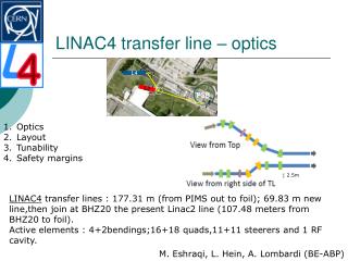
LER transfer line magnet V6 heat load LER transfer line magnet current ramping curve, ramping rate is 210 A/s, first flattop is 15 kA and Second flattop is 55 kA and then there is a long ramping down tails. Using RRR=1000 copper and cool the magnet with 4.6 K helium, the Joule heating within the magnet conductor will be ~ 42 W/m. Total length of conductor is 48 m, so total heat load is 2040 W.
Current leads for fast switching magnets Another heat load for fast switching magnet is caused by heat conduction from current leads. Since each fast switching magnet needs a power supply to energize, the number of PS equals number of magnet.
Current lead heat loads scaled from LHC HTS leads * HTS at CERN & LHC Current Leads by Dr. Amalia Ballarino released at website.
Summary • LER arc magnet will add additional heat load of 346 W for each sector at 4.6 K to 6.0 K level and 5,000 W at 50 – 75 K level. • LER current lead can use the same design as for VLHC design study prototype current lead, which can be used for LER arc magnet ring. • Each fast switching magnet set will add additional 2 kW heat loads at 4.6 K level to the LHC cryogenic system. • Each transfer line magnet set (V6) will add additional 2 kW heat loads at 4.6 K level to the LHC cryogenic system. • Current leads for fast switch magnet will add 312 W at 4.6 K level. • The total cryogenic capacity of current LHC infrastructure is 7700 W at 4.6 K level and 33,000 W at 50 – 75 K level. • Helium inventory for LER ring is only 0.5 L/m, or 1700 kg (or 13 m3). • Helium inventory for fast switching magnets is 0.24 L/m.