Download

1 / 14
170 likes | 550 Views
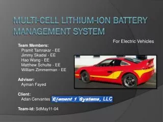
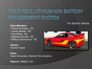
For Electric Vehicle. Team Members Pramit Tamrakar- Electrical Engineering Jimmy Skadal- Electrical Engineering Hao Wang- Electrical Engineering Matthew Schulte- Electrical Engineering Advisor Ayman Fayed Client Adan Cervantes- Element One Systems Team-id - SdMay11-04.

E N D
For Electric Vehicle • Team Members • Pramit Tamrakar- Electrical Engineering • Jimmy Skadal- Electrical Engineering • Hao Wang- Electrical Engineering • Matthew Schulte- Electrical Engineering • Advisor • Ayman Fayed • Client • Adan Cervantes- Element One Systems • Team-id- SdMay11-04 Multi-Cell Lithium-Ion Battery Management System
Project Goals and System Diagram Design a Lithium Ion Battery Charger that is capable of safely charging 16 parallel packs of 90 cells in series. Successfully build a small scale 18 cell charger that is capable of monitoring and balancing the scaled down system.
MSP430 Launch Pad Buck Circuit Bq76pl536EVM-3 Evaluation module For battery management
UCC28019AEVM Boost Circuit Will supply the needed maximum 324 volts to the buck circuit for the large scale charger 350 W Power Factor Correction (PFC) boost converter 390 VDC regulated output 0.9 A of load current Advanced fault protection
Buck circuit and Feedback Loop • The buck circuit will take the voltage generated by the boost buck down to cells • The negative feedback loop • Negative feedback tends to compare actual voltage with desired voltage and seeks to reduce the difference Scaled down buck circuit Value of components
Battery Management System • Texas Instruments bq76PL536EVM-3 and MSP430 microcontroller to monitor and regulate the Li-Ion batteries and send information packet to the processor.
Battery Management System • Programming using C and WinGUI • Use SPI with an MSP430 to gather the data and make decisions based on battery status
Test Plan • Subsystem test: • Boost Converter • System DC supply • Buck Converter • All necessary voltages and currents • Battery Management System communication • USB-SPI Processing GUI • Integration Test (scaled down): • 18 cell charge/discharge • 32.4V-72V CC, 72V CV until 0.3A to batteries