Download
1 / 38
380 likes | 538 Views
DIRC - THE PARTICLE IDENTIFICATION SYSTEM FOR BABAR. Outline: • DIRC Concept and Design • Operational Experience – Performance Highlights – Backgrounds and Longevity • R&D Towards the Future.

E N D
DIRC - THE PARTICLE IDENTIFICATION SYSTEM FOR BABAR • Outline: • • DIRC Concept and Design • • Operational Experience • – Performance Highlights • – Backgrounds andLongevity • • R&D Towards the Future
DIRC grows out of our experience with the ring imaging Cherenkov detector in the SLD experiment, that was founded on a long partnership with Tom Ypsilantis—and called the CRID device. • Blair Ratcliff had the brilliant idea of using the totally internally reflected light transported out to the end of the quartz bar radiators, to be his newly invented PID instrument. • DIRC = CRID Backwards • The DIRC was the creation of a large international collaboration of US and French groups (see names). • It has turned out to be a very robust detector • And, is working very well in BaBar.
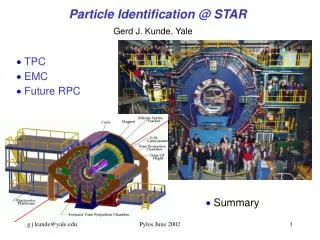
THE COLLABORATION DIRC combines with dE/dx from CDC and SVT (mostly in the 1/b2 region), to provide the hadronic particle identification system for BABAR. ETECTION OF INTERNALLY REFLECTIVE CHERENKOV LIGHT The BABAR-DIRC Collaboration I.Adam,a R.Aleksan,b D.Aston,a D. Bernard,e G.Bonneaud,e P.Bourgeois,b F. Brochard,e D.N.Brown,f J.Chauveau,c J.Cohen-Tanugi,c M.Convery,a S.Emery,b S.Ferrag,e A.Gaidot,b T.Haas,a T.Hadig,a G.Hamel de Monchenault,b C.Hast,d A.Höcker,d R.W.Kadel,f J.Kadyk,f M. Krishnamurthy,h H. Lacker,c G.W.London,b A.Lu,g A.-M.Lutz,d G.Lynch,f G.Mancinelli,i B.Mayer,b B.T.Meadows,i Ll.M.Mir f D.Muller,a J.Ocariz,c S.Plaszczynski,d M.Pripstein,f B.N.Ratcliff,a L.Roos,c M.-H.Schune,d J.Schwiening,a V.Shelkov,f M.D.Sokoloff,i S.Spanier,a J.Stark,c A.V.Telnov,f Ch.Thiebaux,e G.Vasileiadis,e G.Vasseur,b J.Va'vra,a M.Verderi,eW.A.Wenzel,f R.J.Wilson,h G.Wormser,d Ch.Yéche,b S.Yellin,g M.Zito.b a Stanford Linear Accelerator Center b CEA-Saclay, c LPNHE des Universités Paris 6 et Paris 7 d LAL, Universite Paris Sud e Ecole Polytechnique, LPNHE f Lawrence Berkeley National Laboratory g University of California, Santa Barbara h Colorado State University i University of Cincinnati
THE BABAR DIRC 6.5mrad@4GeV/c BaBar requires Particle Identification (PID) up to4.2 GeV/cmomentum. There are two distinct momentum regions and task to be done: • 1.7 p 4.2 GeV/c • p < 2 GeV/c The Particle Identification is achieved using dE/dx information from the Drift Chamber and the silicon vertex detector together with DIRC. [dE/dx is effective for p < 0.7 GeV/c]
THE BABAR DIRC Design Constraints: • CsI Calorimeter needs to detect photons down to 20 MeV, thus small radiation length (< 20%) and small radial size required. • Radiation robustness (expect 10 krad within 10 year lifetime). • p/K separation at 4 GeV/c; this requires 2.2mrad angular resolution, to provide a 3s separation.
THE DIRC IN BABAR DIRC thickness: 8 cm radial incl. supports 19% radiation length at normal incidence DIRC radiators cover: 94% azimuth, 83% c.m. polar angle Instrumented Flux Return 1.5 T Solenoid DIRC Radiators Drift Chamber e+ (3.1 GeV) ElectromagneticCalorimeter e– (9.0 GeV) Silicon Vertex Detector DIRC Standoff Boxand Magnetic Shielding
DIRC PRINCIPLE, PART I • A charged particle traversing a radiator with refractive • index n withb =v/c> 1/nemits Cherenkov photons • on cone with half opening angle cos qc = 1/nb. • If n>2 some photons are always totally internally • reflected for b1 tracks. • Radiator and light guide: Long, rectangular Synthetic Fused Silica (“Quartz”) bars (Spectrosil: average <n(l)> 1.473, radiation hard, homogenous, low chromatic dispersion; • 144 bars: 4901.73.5 cm3, • polished to surface roughness <5Å (rms); • square to better than 0.3 mrad.) • Square radiator bar magnitude • of qc preserved during internal • reflections. • Typical DIRC photon:l 400 nm, ~ 200 bounces, • ~ 10-60 ns propagation time • ~ 5 m average path in bars.
DIRC PRINCIPLE, PART II < ~ • Only one end of bar instrumented; mirror attached to other (forward) end. • Spectrosil wedge glued to readout end reduces required number of PMTs by ~ factor 2 and improves exit angle efficiency for large angle photons . • Photons exit from wedge into expansion region (filled with 6m3 pure, de-ionized water).(<nwater (l)> 1.346, Standoff distance 120 cm, outside main magnetic field; shielding: • B < ~ 1 Gauss) • Pinhole imaging on PMT array(bar dimension small compared to standoff distance).(10,752 traditional PMTs ETL 9125, immersed in water, surrounded by hexagonal “light- • catcher,” transit time spread ~1.5 nsec) • DIRC is a 3-D device, measuring: x, y and timeof Cherenkov photons. • PMT / radiator bar combination plus track direction and location from tracking define qc, fc,tpropagation of photon.
DIRC MEASUREMENTS • DIRC measures photon arrival time at PMT position qc, jc xPMT yPMT tarrival consistency! D t = tarrival - tpropagation • expected uncertainties ~1-2 mrad ~1-4 mrad ~5.4 mrad 2C = 2C,track+ 2C,dispersion + 2C,transport + 2C,imaging +PMT2 ~7.0 mrad per photon: t2~ t2PMT ~(1.7 ns)2 per track: 2C,track trackC ~ photonC/sqrt(Nphotons-per-track)
DIRC RECONSTRUCTION Time information provides powerful tool to reject accelerator and event related background. Calculate expected arrival time of Cherenkov photon based on •track TOF • photon propagation in radiator bar and in water Dt: difference between measured and expected arrival time s(Dt) = 1.7 nsec Dt(nsec) 300 nsec trigger window (~500-1300 background hits/event) • 8 nsec Dt window • (1-2 background hits/sector/event)
DIRC PERFORMANCE Single Photon Cherenkov angle resolution:Dqc,g:difference measured qc,g per photon solution and qc of track fit (di-muons) s(Dqc,g) = 9.6 mrad Expectation: ~9.5 mrad dominated by: 7mrad from PMT/bar size, 5.4mrad from chromatic term, 2-3mrad from bar imperfections. ~10% Background under Dqc,g peak: combinatoric background, track overlap, accelerator background,d electrons in radiator bar, reflections at fused silica/glue interface, ...
DIRC PERFORMANCE Resolution of Cherenkov angle fit per track (di-muons): Number of Cherenkov photons per track (di-muons) vs. polar angle: Between 20 and 60 signal photons per track. s(Dqc,) = 2.4 mradTrack Cherenkov angle resolution is within ~10% of design. Should improve with advances in track- and DIRC-internal alignment. Very useful feature in BABAR environment: higher momentum correlated with larger polar angle values more signal photons, better resolution (~ 1/N )
DIRC OPERATIONAL EXPERIENCE: PHOTON YIELD • Concern: stability of photon yield • Observed PMT front glass corrosion; • No direct experience with maintaining high • (>0.999) radiator reflection coefficient for • 10 years. • Detailed study of photon yield using: • LED pulsercalibration, • PMT aging tests, • comparison of photon yield in real Bhabha and di-muon events separately for every radiator bar • (box). photon yield change per year (%) Consistent result: 1-2% photon yield loss per year. • very minor impact on PID performance over 10 year lifetime of DIRC. barbox number
DIRC OPERATIONAL EXPERIENCE: BACKGROUNDS • PEP-II Luminosity and currents are rapidly increasing • 4*1033 /cm2·snow, • expect >5*1033 /cm2·s atthe end of the 2001/2002 run, • 1-2 *1034 /cm2·sin 2004/5; • 1035 - 1036 /cm2·s discussed(“SuperBABAR”). Dt cut very effective in removing accelerator induced background from reconstruction. But high counting rates cause inefficiency of present DIRC DAQ: ~5% inefficiency at 250 kHz DIRC TDC inefficiency Input frequency (kHz)
DIRC OPERATIONAL EXPERIENCE: BACKGROUNDS In January 2001, installed new, more homogenous lead shielding (5-7cm of lead in upper 2/3, 2-3cm in lower 1/3 of shield). Scaler rates acceptable even above design luminosity. integrated shielding 2001 maximum scaler rate (kHz) Current shielding configuration “background safe” through 2002. New TDC chips to be installed during shutdown Fall 2002: <5% deadtime at 2.5MHz rate. Luminosity (1033/cm2s)
DIRC PARTICLE ID PERFORMANCE kinematically identified p and K D– D0p– K–p + example:2.5<|p|3GeV/c • Select D0 candidate control sample with mass cut (0.5 MeV/c2) • p and K are kinematically identified • calculate selection efficiency and mis-id • Correct for combinatorial background (avg. 6%) with sideband method. e+e- m+m-
DIRC PARTICLE ID PERFORMANCE D– D0p– K–p + D0 K– p+ (11% comb. background) K selection efficiency L K > L p (track in DIRC fiducial, comb. background corrected) p mis-id asK p mis-id as K ~200,000 D0 reconstructed from 9 fb-1 of data. average K selection efficiency: 88% average p mis-id: 2% average rejection factor: 44
DIRC PERFORMANCE—ANOTHER VIEW • MC from Charged Hadron Spectra analysis. • Cuts different than the “standard”…designed to keep mis-ID <1-2% everywhere. • In return, must accept somewhat lower ID efficiency especially a high momenta • Note that mis-ID mis-ID due to different interaction probability.
THE FUTURE • The lab’s goals for the luminosity for PEP-II/BaBar, in the midterm, is to integrate ~ ½ atobarn; • Long-term, there is discussion of a possible 3036 cm-2sec-1 machine delivering 10 atobarn physics sample. • Can we remove the 6 tons of water in DIRC and improve the particle ID performance for this era?
LONG-TERM LUMINOSITY Luminosity Profile“Adiabatic Scenario” LhcB, Btev? Realistic From J. Seeman 10/26/2001
THE R&D PROGRAM • Cosmic ray telescope test bed; • Evaluate new multianode photodetectors; • On the basis of measured performance, work on optimal focusing arrangement.
COSMIC RAY TELESCOPE • Four layers of 13” thick steel absorber to harden muon spectrum (400 MeV to 2.5 GeV in 400 MeV steps). • Trigger counters 1” thick and 60” x 90” • Scintillation hodoscope for tracking • ~1 mrad angular accuracy • ~3 mm spatial accuracy
NEW PHOTODETECTORS Requirement: • compact devices; • good quantum efficiency (20-30%) ; • good spatial resolution (~ mm) ; • good time capability (~ 150 psec) ; • embarking on a program to evaluate performance of the new devices.
NEW PHOTODETECTORS • Hamamatsu flat panel 64-channel PMT [H8500]. Specifications: • 8x8 array of 6 mm x 6 mm pads. • gain ~ a few 106 • rise time < 1 nsec., with 150 psec spread • cross talk ~ few % • gain variation across 64 anodes ~ x 2 • active area 49.7 mm x 49.7 mm • total package size 50.5 mm x 50.5 mm • bi-alkali cathode • 800-1100 volts HV
NEW PHOTODETECTORS • DEP HPD (hybrid photodiodes) • Electrostatically focusing device [HPD PP0380 AU] with 61 channels of 2x2 mm pads. • Proximity focusing device [HPD 0380 AJ] with 73 channels with 2x2 mm pads. Both HDP’s come with direct connection from the pad to the outside world.
Hamamatsu 64-Channel Multi-Anode PMT J. Va’vra J. Va’vra, 1.8.2002
GEOMETRY/OPTICS • Barrel • Use magnetic shielding volume of existing SOB, conceptional geometry • End Cap • With improved performance, /K separation in the forward region could be increased.
R&D PROGRAM SUMMARY • Cosmic ray telescope now beginning operation, • New multianode, single-photon detectors are now in hand, • First results look promising, • Expect interesting results by RICH2002 and IEEE2002.
CONCLUSIONS • Brilliant idea for a /K detector in B factory energy regime! • Robust device delivering close to promised performance. • Particle Identification is important in almost all BaBar physics analyses. • With the current upgrade of DAQ electronics should be OK up to luminosities x10 design (1034 cm-2 sec-1). • R&D for improved PID performance, and to survive in a high-luminosity environment, is under way-- expect results in Fall of 2002.
Please join me in thanking our hosts for their hospitality and this stimulating conference—continuing a long line of such meetings, since 1977. I have the privilege in welcoming you all to the next meeting of the Instrumentation for Colliding Beams in 2005, to Stanford—hosted by SLAC and Stanford University. I wish you all safe travels home!