Download
1 / 49
520 likes | 679 Views
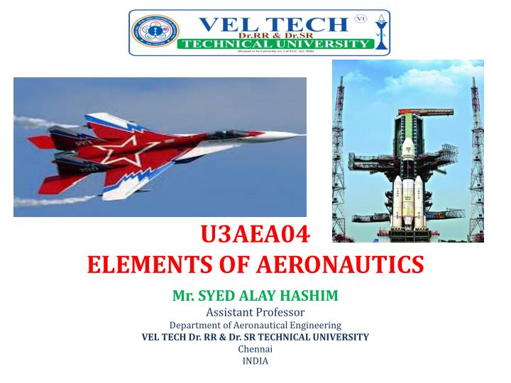
U3AEA04 ELEMENTS OF AERONAUTICS. Mr. SYED ALAY HASHIM Assistant Professor Department of Aeronautical Engineering VEL TECH Dr. RR & Dr. SR TECHNICAL UNIVERSITY Chennai INDIA. I to V UNIT POWER POINT PRESENTATION. AIRCRAFT COMPONENTS. TYPES OF WING. Monoplane Biplane Tandem wing

E N D
U3AEA04ELEMENTS OF AERONAUTICS Mr. SYED ALAY HASHIM Assistant Professor Department of Aeronautical Engineering VEL TECH Dr. RR & Dr. SR TECHNICAL UNIVERSITY Chennai INDIA
I to V UNIT POWER POINT PRESENTATION
TYPES OF WING • Monoplane • Biplane • Tandem wing • Triplane • Quadruplane • Multiplane • Canard wing
AIRCRAFT HISTORICAL RECORDS
IntroductionAEROSPACE ENGINES • Comprehend the basic components of gas turbine engines and their basic operations • Comprehend the thermodynamic processes occurring in a gas turbine engines • Comprehend the support systems associated with gas turbine engines
Gas Turbine Cycle Single stage Ideal gas turbine cycle Gas Turbine Cycle Two stage turbine cycle
Gas Turbine Cycle Two stage Compressor and Turbine cycle
Jet Propulsion Cycle In practical or actual cycle Entropy is not constant
Compressor • Supplies high pressure air for combustion process • centrifugal flow and Axial flow • Centrifugal Compressor • Adv: simple design, good for low compression ratios (5:1), strong • Disadvantage: Difficult to stage, less efficient, high frontal area
Compressor • Axial flow • Good for high compression ratios (20:1) • Most commonly used
Turbine • Convert the kinetic energy into expansion work • It is used to drive the compressor as well as • propeller shaft
Classification of Engine Engine Air Breathing Engine Non-Air Breathing Engine (Using atm air to produced Power) (Presents of Fuel and absents of Air instead of Air + Oxidizer. Hypersonic vehicles, Operating Mach No : 15 to 20) Jet Engines Reciprocating Engines (Propulsive thrust is produced by jet) Rocket Engine (No moving parts) Gas Turbine Engine Non-Gas Turbine Engine (No moving parts) (Available moving parts like Compressor and Turbine) Ramjet Scramjet Pulsejet Turbojet Turboprop Turbofan Turbo-shaft
Turbojet • Chemical energy is converted into mechanical energy • 100% Thrust produced by Nozzle • Operating Mach No: 1 to 2 • Supersonic Aircraft (1 to 5)
Turbofan • 20 to 40% of Thrust produced by Nozzle • 60 to 80% of Thrust produced by Fan • Operating Mach No: 0.4 to 0.8 • High Subsonic Aircraft (0.3 to 0.8)
Turboprop • 20 to 25% of Thrust produced by Nozzle • 75 to 80% of Thrust produced by Propeller • Operating Mach No: 0.4 to 0.65 • Subsonic Aircraft (0.1 to 0.8)
Turbo Shaft • High pressure turbine is used to rotate HP & LP Compressor • Low pressure turbine is used to rotate output Shaft • No Thrust produced in the exit turbine gas
Turbo Shaft • Kinetic energy is converted to Shaft power • 100% Thrust produced by Shaft • Operating Mach No: 0.4 to 0.8 • High speed Subsonic helicopter (0.3 to 0.8)
Pulse Jet • Made up of few moving parts • Valved engines use a mechanical valve to control the flow of expanding exhaust, forcing the hot gas to go out the back of the engine through the tailpipe • Starting the engine usually requires forced air and an ignition method such as a spark plug for the fuel-air mix. • It can operate statically
Rocket Engines • A rocket is a machine that develops thrust by the rapid expulsion of matter • A rocket is called a launch vehicle when it is used to launch a satellite or other payload into space • Rocket engines are reaction engines • The highest exhaust velocities • It is used in missile
Thrust Equation • Total Thrust = Momentum Thrust + Pressure Thrust • mi=mj (mass flow rate) • Inlet pressure = Exit pressure • Thrust force is the forward motion of engine
Factors Affecting Thrust • PRESSURE • TEMPERATURE • DENSITY • HUMIDITY • ALTITUDE • FORWARD VELOCITY
Methods of Thrust Augmentation • After burning • High thrust for short duration • It is used only in take-off (or) for high climbing rates • Additional fuel is burning in the tail pipe between the turbine and exhaust nozzle • It is increased the jet velocity • Oxidizer-Fuel Mixture • Increase the mass flow rate • Evaporative cooling which produces higher pressure and higher mass flow rate • Increase the compressor pressure ratio due to reduced compressor air flow • Water and menthol or alcohol Mixture
Oxidizer-Fuel Mixture • Evaporative cooling which produces higher pressure and higher mass flow rate
Advantages of Gas turbine Engines • Weight reduction of 70% • Simplicity • Reduced manning requirements • Quicker response time • Faster Acceleration/deceleration • Modular replacement • Less vibrations • More economical
Disadvantages of Gas Turbine Engines • Many parts under high stress • High pitched noise • Needs large quantities of air • Large quantities of hot exhaust (target) • Cannot be repaired in place