Download
1 / 41
410 likes | 420 Views
The 4 n =1 resonance of a high intensity linac. D. Jeon (SNS) I. Hofmann, L. Groening, G. Franchetti (GSI) HB 2008 August 25-29, 2008. This work is the result of the collaboration between GSI and SNS. Thanks to J. Galambos, S. Henderson for the support. History of halo formation mechanisms.

E N D
The 4n=1 resonance of a high intensity linac D. Jeon (SNS) I. Hofmann, L. Groening, G. Franchetti (GSI) HB 2008 August 25-29, 2008
This work is the result of the collaboration between GSI and SNS. • Thanks to J. Galambos, S. Henderson for the support. Presentation_name
History of halo formation mechanisms • Until 1998, mismatch was the only known mechanism of halo formation. • Late 1998, halo formation by the 2nx - 2ny =0 resonance in the ring was discovered by D. Jeon (presented by J. Holmes at PAC99) leading to other resonance induced halo studies in the ring. • Since then coupling resonance in the linac has been studied extensively by many. • Other halo formation mechanisms have been discovered such as non-round beam (D. Jeon, APAC07), rf cavity (M. Eshraqi) etc. • Widely believed that there is no other resonance in the linac… Presentation_name
Review Non-Round Beam induced Halo Formation Optics modification improves beam quality z Nominal SNS MEBT Optics Round Beam MEBT Optics Presentation_name
Round Beam Optics improves X beam quality (Emittance Measurement) Round Beam Optics reduces halo and rms emittance in X significantly Nominal Optics eX= 0.349 mm-mrad (1% threshold) 0.454 mm-mrad (0% threshold) Round Beam Optics eX= 0.231 mm-mrad (1% threshold) 0.289 mm-mrad (0% threshold) Presentation_name
Tail is significantly reduced for Round Beam Optics Round Beam Optics reduces beam tail visibly This tail is the source of beam loss in downstream linac Nominal Optics Measured Round Beam Optics Measured No Tail!! Presentation_name
Round Beam Optics improves Y beam quality (Emittance Measurement) Round Beam Optics reduces halo and rms emittance in Y significantly Nominal Optics eY= 0.353 mm-mrad (1% threshold) 0.472 mm-mrad (0% threshold) Round Beam Optics eY= 0.264 mm-mrad (1% threshold) 0.306 mm-mrad (0% threshold) Presentation_name
Envelope instability • Envelope equation predicts envelope instability at 90° phase advance. • Linac design including the SNS linac has avoided the 90° phase advance because of the envelope instability! • GSI UNILAC has the capability to scan well beyond 90° phase advance + emittance scanner. • D. Jeon made a proposal to GSI to do an experiment to measure the stop-band of the envelope instability. Presentation_name
SNS Linac design Phase & Quad Laws Avoid the Envelope Instability and the Coupling Resonance Presentation_name
Discovery of the 4n=1 resonance of a linac driven by space charge • Linac simulation study finds the 4n=1 resonance when the depressed phase advance is about 90°, rather than the envelope instability. • This 4n=1 resonance is dominating over the better known envelope instability and practically replacing it. • It should be stated that linac design should avoid 90° phase advance because of the 4n=1 resonance rather than the envelope instability!! Presentation_name
4n=1 resonance crossing from below • rms emittance • phase advance Presentation_name
Beam distribution when crossing the 4n=1 resonance from below Initial beam distribution X’ Y’ X Y Presentation_name
4n=1 resonance crossing from above • rms emittance • phase advance Presentation_name
Beam distribution when crossing the 4n=1 resonance from above • Stable fixed points move from the origin afar. • This traps beam particles. X’ Y’ Y X Presentation_name
No resonance effect s > 90º When s ~ 95° • rms emittance • phase advance Presentation_name
It seems that no resonance effect s > 90º When s ~ 95° X Y Presentation_name
It seems that no resonance effect s > 90º When s ~ 95° X’ Y’ X Y There is no sign of resonance effect on the beam distribution Presentation_name
Resonance takes effect for s <= 90º When s ~ 85° • Emittance growth when s <= 90° • rms emittance • phase advance Presentation_name
resonance effect s <= 90º When s ~ 85° X Y Presentation_name
resonance effect s <= 90º When s ~ 85° X’ Y’ X Y Presentation_name
Effects of input beam mismatch effects of resonance and mismatch manifest well matched X’ Y’ X Y mismatched Presentation_name
Scaling law when crossingthe 4n=1 resonance • Emittance growth is a function of S≡ DnDn = (Dn)2/(dn/dn). (I. Hofmann et al) • e (1 + aDnDn) eo • De/eo aDnDn • For the linac 4n=1 resonance, the emittance growth is a linear function of DnDn. Presentation_name
Scaling law when crossing the resonance • De/eo aDnDn = aS. • For downward 4n=1 resonance crossing, a 0.31 • For upward 4n=1 resonance crossing, a 0.37 a=0.37 a=0.31 Presentation_name
Emittance growth for fixed phase advance • roughly proportional to X3.5 X Presentation_name
Efforts to measure the 4n=1 resonance stop-band using the GSI UNILAC • Simulated erms vs s0 at the end of Tank A1 of UNILAC. • About 45% of rms emittance increase is anticipated. • New emittance scanner to be installed between Tank A1 and A2. Presentation_name
Summary • Discovery of a new halo formation mechanism, 4n=1 resonance for a linac was made. • This is one step forward to Grand Unification of Linac and Ring beam dynamics. • Linac design should avoid 90° phase advance because of the 4n=1 resonance rather than the better known envelope instability!! • Efforts are undertaken to measure the 4n=1 resonance stop-band at GSI, Germany. • Is envelope instability a theoretical artifact?? Presentation_name
Thanks for the attention. Presentation_name
Fraction of core in x plane sees nonlinear space charge force, resulting in halo formation in x plane Beam at the chopper target potential halo Space charge force and real space distributions Presentation_name
Sources of Front End halo generation • MEBT is the largest contributor to FE halo generation • Nonlinear space charge force stemming from a large transverse • beam eccentricity generates halo in MEBT • (D. Jeon et al, PRST-AB 5, 094201 (2002)) • As minor contributors, several FE components and physical effects • may contribute to the generation of beam halo Chopper target MEBT optics Z X RFQ DTL Y Beam ~1.6 m Region with a large transverse beam eccentricity ~2:1 Presentation_name
Optics modification alone reduces halo significantly in simulations (Simulation) Half optics modified Nominal Optics Round Beam Optics CCL bore Presentation_name
Tail is significantly reduced for Round Beam Optics Round Beam Optics reduces beam tail visibly This tail is the source of beam loss in downstream linac Round Beam Optics Measured No Tail!! Nominal Optics Measured Presentation_name
Gesellschaft für SchwerIonenforschung GSI Synchrotron, Br= 18 Tm p: 4 GeV Ne: 2 GeV U: 1 GeV 3 sources Fragment Separator Stor. Ring, Br = 10 Tm UNILAC, p – U : 3 – 12 MeV/u High Energy Physics ion species vary from pulse to pulse: simultaneous experiments using different ions Presentation_name
FAIR: Facility for Antiproton and Ion Research 71010 cooled pbar / hour 100 m Presentation_name
UNILAC at GSI: Overview Single Gap Resonators RFQ, IH1, IH2 Alvarez DTL Transfer to Synchrotron HLI: (ECR,RFQ,IH) MEVVA MUCIS Alvarez DTL RFQ IH1 IH2 U4+ U28+ PIG Gas Stripper 11.4 MeV/u β = 0.16 2.2 keV/u β = 0.0022 120 keV/u β = 0.016 1.4 MeV/u β = 0.054 Presentation_name
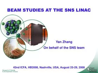
Set-up for Measurements • Beam Current Measurement • Beam Emittance Measurement (transv.) • Beam Profile Measurement Matching to DTL from HSI Alvarez DTL Section SGR Gas Stripper 40Ar1+ 40Ar10+ Presentation_name
UNILAC at GSI : Requirements (Uranium) SIS 18 Injection 238U73+ 4.6 4.2·1010 11.4 ±2·10-3 0.8 Design: 4.6 mA, Status 2001: 0.37 mA, Status today: 2.0 mA Presentation_name
Benchmarking efforts at GSI • It needs to better understand the UNILAC for higher beam current requirement of FAIR project. • GSI waged a campaign of measuring the output beam emittance, varying the zero current phase advance from 35° to 90°. • Efforts to compare the experiment with simulation of codes. • Three different codes have been used: DYNAMION (GSI), PARMILA, PARTRAN (France). Presentation_name
Code benchmarking effort comparing exp (100%) and simulation (100%) • Comparison of 100% rms emittance suffers from noise in measurement data Presentation_name
Code benchmarking effort comparing exp (90%) and simulation (95%) • Gap between experiment and simulation narrows. Presentation_name
Code benchmarking effort comparing exp (95%) and simulation (95%) • Coming soon!! Presentation_name