Download
1 / 1
10 likes | 243 Views
HIGH POWER RF TESTS OF THE FIRST MODULE OF THE TOP LINAC SCDTL STRUCTURE C. Ronsivalle, L. Picardi, C. Cianfarani, G. Messina, G.L. Orlandi, (ENEA-Frascati,Italy) E.Cisbani, S.Frullani, (Istituto Superiore di Sanità, Roma, Italy) . Abstract

E N D
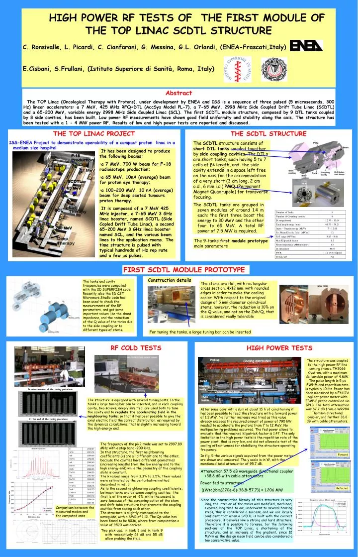
HIGH POWER RF TESTS OF THE FIRST MODULE OF THE TOP LINAC SCDTL STRUCTURE C. Ronsivalle, L. Picardi, C. Cianfarani, G. Messina, G.L. Orlandi, (ENEA-Frascati,Italy) E.Cisbani, S.Frullani, (Istituto Superiore di Sanità, Roma, Italy) Abstract The TOP Linac (Oncological Therapy with Protons), under development by ENEA and ISS is a sequence of three pulsed (5 microseconds, 300 Hz) linear accelerators: a 7 MeV, 425 MHz RFQ+DTL (AccSys Model PL-7), a 7-65 MeV, 2998 MHz Side Coupled Drift Tube Linac (SCDTL) and a 65-200 MeV, variable energy 2998 MHz Side Coupled Linac (SCL). The first SCDTL module structure, composed by 9 DTL tanks coupled by 8 side cavities, has been built. Low power RF measurements have shown good field uniformity and stability along the axis. The structure has been tested with a 1 - 4 MW power RF. Results of low and high power tests are reported and discussed. THE TOP LINAC PROJECT ISS-ENEA Project to demonstrate operability of a compact proton linac in a medium size hospital THE SCDTL STRUCTURE The SCDTL structure consists of short DTL tanks coupled together by side coupling cavities. The DTLs are short tanks, each having 5 to 7 cells of βλ length, and the side cavity extends in a space left free on the axis for the accommodation of a very short (3 cm long, 2 cm o.d., 6 mm i.d.) PMQ (Permanent Magnet Quadrupole) for transverse focusing. • It has been designed to produce the following beams: • a 7 MeV, 700 W beam for F-18 radioisotope production; • a 65 MeV, 10nA (average) beam for proton eye therapy; • a 100-200 MeV, 10 nA (average) beam for deep seated tumours proton therapy. • It is composed of a 7 MeV 425 MHz injector, a 7-65 MeV 3 GHz linac booster, named SCDTL (Side Copled Drift Tube Linac), a second 65-200 MeV 3 GHz linac booster named SCL, and the various beam lines to the application rooms. The time structure is pulsed with typical hundreds of Hz rep rate and a few s pulses. The SCDTL tanks are grouped in seven modules of around 1.4 m each: the first three boost the energy to 30 MeV and the other four to 65 MeV. A total RF power of 7.5 MW is required. The 9-tanks first module prototype main parameters FIRST SCDTL MODULE PROTOTYPE Construction details The tanks and cavity frequencies were computed with the 2D SUPERFISH code. Recently, also the 3D CST Microwave Studio code has been used to check the measurements of the RF parameters, and get some important values like the shunt impedance, and the reduction of the Q value of the tanks due to the side coupling or to different types of stems. The stems are flat, with rectangular cross section, 4x12 mm, with rounded edges in order to make the cooling easier. With respect to the original design of 5 mm diameter cylindrical stems, however, the reduction is 10% on the Q value, and not on the Zsh/Q, that is considered really tolerable For tuning the tanks, a large tuning bar can be inserted RF COLD TESTS HIGH POWER TESTS The structure was coupled to the high power RF line coming from a TH2066 Klystron, with a maximum deliverable power of 4 MW. The pulse length is 5 μs FWHM and repetition rate is typically 10 Hz. Power has been measured by a E4117A Agilent power meter with EPMP-P probe controlled via GPIB. The total attenuation was 57.7 dB from a WR284 Thomson directional coupler, and further 38.8 dB with cable attenuators. In some moment of the tuning procedure The structure is equipped with several tuning posts. In the tanks a large tuning bar can be inserted, and in each coupling cavity, two screws, deeply inserted, are used both to tune the cavity and to regulate the accelerating field in the neighbouring tanks, so that it has been possible to give the axial electric field the correct distribution, as required by the dynamics calculations, that is slightly increasing toward the high energy end. After some days with a sum of about 15 h of conditioning it has been possible to feed the structure with a forward power of 1.2 MW. No further increase was tried as this value already exceeds the required amount of power of 790 kW needed to accelerate the protons from 7 to 12 MeV. No multipactoring problems occurred. The fed power allows to evaluate that the reached Kilpatrick factor is 1.47. The only limitation in the high power tests is the repetition rate of the power plant, that is very low, and did not allowed a test of the cooling effectiveness for stabilizing the structure operating frequency. In fig. 5 the various signals acquired from the power meter are shown and compared. The y scale is in W, with the mentioned total attenuation of 95.7 dB. At the end of the tuning procedure The frequency of the pi/2 mode was set to 2997.89 MHz with a stop band <200 kHz. In this structure, the first neighbouring coefficients (k) are all different one to the other, because the cavities have different geometries (increasing lengths from the low energy end to the high energy end) while the geometry of the coupling slots is constant. The k values range from 3.3% to 3.5%. Their values were estimated by the perturbative method described in ref. 3. As to the second neighbouring coupling coefficients, between tanks and between coupling cavities, the first is of the order of -1%, while the second is zero, because of the screening action of the stem and drift tube structure that prevents the coupling cavities from seeing each other. The structure is slightly overcoupled to the waveguide, with a SWR of 1.12. The Qo value has been found to be 8036, where from computation a value of 9520 was derived. Forward Attenuation:57.5 dB waveguide directional coupler +38.8 dB with cable attenuators Power fed to structure: ((WtoDbm(270e-6)+38.8+57.7)) = 1.206 MW Reflected Since the construction history of this structure is very long, the interior of the tanks was modified, machined, exposed long time to air, underwent to several brazing steps, this is considered a success, and we are largely confident that when a SCDTL is built with the correct procedure, it behaves like a strong and hard structure. Therefore it is possible to foresee, for the following sections of the TOP Linac, a shortening of the structure, and an increase of the gradient, since 12 MV/m as the design mean field can be also considered a too conservative value. Comparison between the measured modes and the computed ones Two pick-ups, in tank 1 and in tank 9 with respectively 52 dB and 55 dB allow probing the field.