Download
1 / 12
120 likes | 270 Views
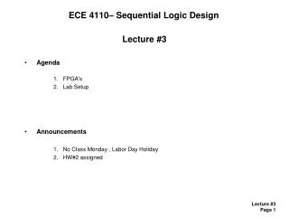
ECE 4110– Sequential Logic Design. Lecture #23 Agenda Latches and Flip-Flops Review Announcements HW #11assigned. Latches. Latches - we’ve learned all of the VHDL syntax necessary to describe sequential storage elements - Let’s review where sequential devices come from

E N D
ECE 4110– Sequential Logic Design Lecture #23 • Agenda • Latches and Flip-Flops Review • Announcements • HW #11assigned.
Latches • Latches- we’ve learned all of the VHDL syntax necessary to describe sequential storage elements- Let’s review where sequential devices come from • SR Latch- To understand the SR Latch, we must remember the truth table for a NOR Gate AB F 00 1 01 0 10 0 11 0
Latches • SR Latch- when S=0 & R=0, it puts this circuit into a Bi-stable feedback mode where the output is either:Q=0, Qn=1 Q=1, Qn=0AB FAB F 00 1 (U2) 00 1 (U1) 01 0 01 0 (U2) 10 0 (U1) 10 0 11 0 11 0 0 0 0 1 1 0 0 1 1 0 0 0
Latches • SR Latch- we can force a known state using S & R:Set (S=1, R=0)Reset (S=0, R=1) AB FAB F 00 1 (U1) 00 1 (U2) 01 0 01 0 (U1) 10 0 (U2) 10 0 11 0 (U2) 11 0 (U1) 0 1 1 0 0 1 1 0 0 1 1 0
Latches • SR Latch- we can write a Truth Table for an SR Latch as followsS R Q Qn . 0 0 Last Q Last Qn - Hold 0 1 0 1 - Reset 1 0 1 0 - Set 1 1 0 0 - Don’t Use- S=1 & R=1 forces a 0 on both outputs. However, when the latch comes out of this state it is metastable. This means the final state is unknown.
Latches • S’R’ Latch- we can also use NAND gates to form an inverted SR LatchS’ R’ Q Qn . 0 0 1 1 - Don’t Use 0 1 1 0 - Set 1 0 0 1 - Reset 1 1 Last Q Last Qn - Hold
Latches • SR Latch w/ Enable- we then can add an enable line using NAND gates- remember the Truth Table for a NAND gateAB F 00 1 - a 0 on any input forces a 1 on the output 01 1 - when C=0, the two EN NAND Gate outputs are 1, which forces “Last Q/Qn” 10 1 - when C=1, S & R are passed through INVERTED 11 0
Latches • SR Latch w/ Enable- the truth table then becomesC S R Q Qn . 1 0 0 Last Q Last Qn - Hold 1 0 1 0 1 - Reset 1 1 0 1 0 - Set 1 1 1 1 1 - Don’t Use 0 x x Last Q Last Qn - Hold
Latches • D Latch- a modification to the SR Latch where R = S’ creates a D-latch- when C=1, Q <= D- when C=0, Q <= Last ValueC D Q Qn . 1 0 0 1 - track 1 1 1 0 - track 0 x Last Q Last Qn - Hold
Latches • VHDL of a D Latch architecture Dlatch_arch of Dlatch is begin LATCH : process (D,C,Q) begin if (C=‘1’) then Q<=D; Qn<=not D; else Q<=Q; Qn<=Qn; end if; end process; end architecture;
Flip Flops • D-Flip-Flops- we can combine D-latches to get an edge triggered storage device (or flop) - the first D-latch is called the “Master”, the second D-latch the “Slave”MasterSlave CLK=0, Q<=D “Open” CLK=0, Q<=Q “Close” CLK=1, Q<=Q “Closed” CLK=1, Q<=D “Open” - on a rising edge of clock, D is “latched” and held on Q until the next rising edge
Flip Flops • VHDL of a D-Flip-Flop architecture DFF_arch of DFF is begin FLOP : process (CLK) begin if (CLK’event and CLK=1) then -- recognized by all synthesizers as DFF Q<=D; Qn<=not D; else Q<=Q; Qn<=Qn; end if; end process; end architecture;