Download
1 / 20
300 likes | 520 Views
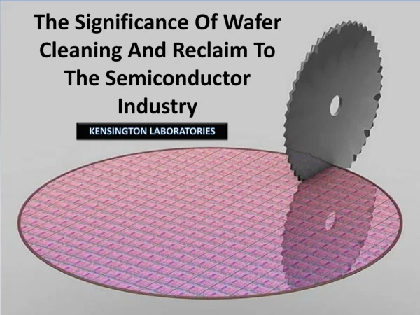
Optimizing high frequency ultrasound cleaning in the semiconductor industry. Steven Brems. Outline. Introduction to particle removal Improving state-of-the-art megasonic cleaning Acoustic pulsing Oversaturated liquids Traveling waves

E N D
Optimizing high frequency ultrasound cleaning in the semiconductor industry Steven Brems
Outline • Introduction to particle removal • Improving state-of-the-art megasonic cleaning • Acoustic pulsing • Oversaturated liquids • Traveling waves • Future of particle removal with liquid motion in the semiconductor industry • Conclusions
v F Introduction: Particle cleaning Particle attached to wafer surface Breaking of theVan der Waals forces(under)etching Lift-off from surface: repulsive forces(electrostatic: z) Transport away fromsurface: diffusion,convection Mechanism of particle removal by pure chemical cleaning 20 nm 200 nm • Nanoparticle removal with pure chemical cleaning is only effective if >2 nm material is removed. • A combination of physical and chemical cleaning methods will become more important
Outline • Introduction to particle removal • Improving state-of-the-art megasonic cleaning • Acoustic pulsing • Oversaturated liquids • Traveling waves • Future of particle removal with liquid motion in the semiconductor industry • Conclusions
Towards a control of bubble size: Pulsing Pulse on time Pulse off time • At sufficiently high gas concentration and acoustic pressures, bubbles can grow by rectified diffusion and bubble coalescence • Microbubbles (< 4 mm) will always shrink when ultrasound is turned off and dissolved gas saturation is below 130% • Bubbles could kept around resonance radius by turning the acoustic field on (bubbles grow) and off (bubbles dissolve) J. Lee et al., JACS 127, 16810 (2005)
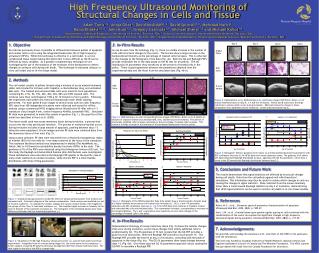
In-situ measuring micro-bubble activity Example of cavitation noise spectra Hydrophone amplifier oscilloscope Wafer Transducer • Bubble oscillation • Frequency distribution of the oscillating bubble motion can contain harmonics, subharmonics and ultraharmonics • The components arise from the nonlinear motion of a bubble acoustic emission • Non-integer harmonics (5f0/2, 7f0/2, 9f0/2…) : • Particular characteristic of non-linear (stable) bubble motion • Can be used as an indicator for bubble activity • Strong (transient) cavitation produces white noise (increase of background signal) • Instable cavitation = damaging cavitation
Cavitation noise spectra: Influence of pulses -8dB=40% DC 10% DC 25% DC 50% • Experimental details • Oxygen concentration: 120 %, applied power: 640 mW/cm2 • Duty Cycle is varied • Optimal pulse off time (indicated with ) is independent of duty cycle variation • Bubble activity decreases with increasing duty cycle • However, a lower DC also means a lower effective cleaning time!
Understanding of optimal pulse off time ~ resonant bubble size Production of new bubbles (transient collapse, shape instabilities) The dissolution time of a resonant bubble lies very close to the optimal experimental determined pulse off time Growing to active size during pulse-on time Inactive bubbles that continue to grow or active bubbles that grow out of resonance Dissolution during pulse-off time Bubble size distribution centered around resonance radius ‘reservoir’ Dissolved oxygen concentration 120% Lost bubbles Dissolution time resonant bubble Bubble size
Cavitation Activity: Role of On-Time Pulse on time variation at constant pulse off time (150 ms) and 105 % dissolved gas Cavitation noise data tgrow= 8.6 ms teff=1.1 s Pulse on times Lost bubbles Reservoir Bubble size • A simple bubble model based on bubble growth, bubble loss and bubble creation mechanisms can model the pulse on time variation. • A maximum bubble activity is reached with a pulse on time of ~50 ms
Influence of pulse off time PRE maps for variable pulse off times, a fixed pulse on time (50 ms) and a dissolved oxygen concentration of 105% Acoustic pulsing noticeably improves particle removal without changing acoustic power densities 100 • Acoustic field 145 mm from transducer surface • Non-uniform acoustic field is a near-field (interference) effect caused by the transducer size. • Non-uniform fields result in localized cleaning. PRE (%) 50 0 Experiment Simulation
Outline • Introduction to particle removal • Improving state-of-the-art megasonic cleaning • Acoustic pulsing • Oversaturated liquids • Traveling waves • Future of particle removal with liquid motion in the semiconductor industry • Conclusions
Maximazing bubble formation PRE as function of dissolved oxygen concentration 90% 100% 110% 120% 125% 130% Impossible to nucleate bubbles Bubbles do not dissolve anymore 100 Duty cycle is 10%, pulse off time is optimized for dissolved gas concentrations and applied power is 420 mW/cm2. PRE (%) 50 The optimal dissolved gas concentration facilitates bubble formation ( ≥ 100%) and enables bubble dissolution ( < 130%) 0 • Bubble formation is limiting the megasonic cleaning efficiency. • An increased dissolved gas concentration facilitates the nucleation of bubbles
Upper limit dissolved gas concentration This term determines bubble growth or dissolution Bubble resonance size Growth Dissolution • Bubble dissolution or growth in the absence of an acoustic field is given by
Outline • Introduction to particle removal • Improving state-of-the-art megasonic cleaning • Acoustic pulsing • Oversaturated liquids • Traveling waves • Benchmarking of physical cleaning techniques • Future of particle removal with liquid motion in the semiconductor industry • Conclusions
Increasing PRE: transport of bubbles towards the wafer surface • Simulation of a 2.7 mm sized bubble (radius) in an acoustic field of 0.73 W/cm2. The average bubble velocities is in the order of m/s. • Standing wave field • Bubbles experience an acoustic radiation force (Bjerkness force): • At moderate acoustic powers, bubbles smaller (larger) than resonance size will travel up (down) a pressure gradient. So small bubbles go to pressure antinodes and large bubbles go to pressure nodes. • Traveling wave • To simulate bubble motion in a traveling wave, acoustic radiation force, added mass force (inertia) and viscous drag force need to be taken into account. As a result, radial and translational equations are coupled.
Influence of a traveling wave on particle removal efficiency Transducer Wafer Damping material • A silicon wafer is transparent for acoustic waves at a specific angle • With the combination of damping material, a traveling wave can be formed • Bubbles are transported towards the wafer surface and improve particle removal
Outline • Introduction to particle removal • Improving state-of-the-art megasonic cleaning • Acoustic pulsing • Oversaturated liquids • Traveling waves • Future of particle removal with liquid motion in the semiconductor industry • Conclusions
Large particles Particle cleaning with liquid motion Small particles Boundary layer thickness >> 100 nm 200 nm 100 nm 100 nm 30 nm Although the removal force increases for larger particles, it gets easier to remove large particles because drag force scales with radius and velocity A structure with a high aspect ratio gets problematic, due to a strong increase in drag force on that structure Physical cleaning techniques based on a fluid flow are ideally suited to remove ‘larger’ particles.
Conclusions • System optimization • Experimental megasonic system is optimized • Controlling average bubble size with acoustic pulsing • Facilitating bubble nucleation with slightly oversaturated liquid • Transporting bubbles towards wafer surface with traveling waves • Challenges • Megasonic cleaning uniformity needs to be solved • Cleaning of 30 nm and smaller silica particles with low damage levels is not yet achieved • Boundary layer and aspect ratio of structures makes current techniques not suitable for continued scaling
Acknowledgements • Thanks to • Marc Hauptmann, Elisabeth Camerotto, Antoine Pacco, Geert Doumen, Stefan De Gendt, Marc Heyns, Geert Doumen and Tae-Gon Kim (Imec) • Christ Glorieux (KULeuven) • Aaldert Zijlstra (University of Twente) Antoine Pacco