Download
1 / 28
280 likes | 361 Views
Design and produce an Analog VLSI Cochlea with AER output interface using Pseudo Floating-Gate Inverters as transconductors. Explore the functioning of the human ear and the complex mechanisms of cochlear processing. Implement circuitry to replicate the inner hair cell transduction process. Conduct simulations and analysis for optimal performance.

E N D
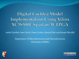
An AER Analog Silicon Cochlea Model using Pseudo Floating Gate Transconductors Master Thesis in Electronics and Computer Science, Microelectronics Programme, University of Oslo by: Hans Kristian Otnes Berge
Thesis assignment • Design and produce an Analog VLSI Cochlea with an Adress-Event Representation (AER) output interface, using Pseudo Floating-Gate Inverters as transconductors.
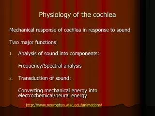
The Human Ear • Sound waves set the middle ear bones in motion. • Amplification from the tympanic membrane to the oval window. • The cochlea converts the waves into a neural code.
The Cochlea • Oval window movement causes a travelling wave on the Basilar Membrane (BM). • The inner hair cell (IHC) transforms the motion into a neural signal. Unrolled cochlea
Cochlea tuning curves • Large sensitivity range, almost 6 orders of magnitude. • A BM site responds best to a Characteristic Frequency (CF) • CF’s gradually change from high at the base to low at the apex.
Inner Hair Cell (IHC) Transduction • Molecular chains open ion channels in the tips of the stereocilia. • Ions flow through the channels and activate voltage gated ion channels along the IHC lateral wall. • Glutamate is released from the base into synapses leading to Auditory Nerves (AN).
Circuit implementation • Cascaded second order filters approximate basilar membrane response. • Halfwave rectification and integrate&fire neurons approximate IHC&AN response. • Digital circuits handle the output spikes and transmit these on a common bus.
Second order filter Second order section using differential transconductance amplifiers. • Similar response compared to BM response curves. • Cascaded second order sections provide pseudo-resonance and steep roll-off. Simulation of 32 cascaded second order sections. Normalized response of several cascaded ideal second order sections with a gradient of fc’s.
Pseudo Floating-GateSecond order filter (Left) Varying the filter cut-off by varying the bias voltages of the first and second inverter by the same amount. (Right) The second order section implemented with Pseudo Floating-Gate Inverters (Left) Varying the filter Q by adjusting the bias voltages of the first and second inverter independently. (Right) Typical mean ac simulation of 32 cascaded second order sections.
Pseudo Floating-Gate (PFG) Inverter • An inverting amplifier. • Transconductance and output offset is tuned by a pair of voltages Vp, Vn. • May have many inputs.
Pseudo Floating-Gate InverterSimplified Small Signal Model May use C3 to increase attenuation in the stop-band somewhat. It may also be used to attenuate noise at Vp and Vn nodes. Mismatch between C1 and C2 may affect low-frequency gain and cut-off frequency. The amount of mismatch shown here is +- 5%
Pseudo Floating-Gate InverterMonte Carlo Simulations • Simulating process and mismatch variation with zero device correlation (worst case). W/L = 50/0.35 W/L = 50/2 Output offset variation between two equally biased PFG inverters. Short transistors have lower gain. Cutoff (-3dB) ratio (fc1/fc2) between two equally biased PFG inverters. The denominator cutoff is along the x-axis. Variations in low-frequency gain of a PFG inverter. W/L = 50/0.35 W/L = 50/0.35
Pseudo Floating-GateBiasing Circuits • Was a major difficulty with the work in this master project. • Non-linear circuits may exhibit chargepumping: • For low Vth processes, the channel current dominates for a diode-connected transistor at zero gate-source voltage. Above: Some earlier proposed bias structures implementable in CMOS. Below: Two proposed structures, not directly implementable in CMOS.
Pseudo Floating-GateBiasing Circuits • The employed bias circuit unfortunately failed to operate correctly, although a very similar structure had been tried&tested earlier. Later Monte-Carlo simulations showed that the structure should have a yield of only 15%, mostly due to Vth mismatch.
Inner hair cell &Auditory Nerve Circuit (1) Voltage-to-Current Rectification
Inner hair cell &Auditory Nerve Circuit (2) Leaky integrate and fire neuron Simulation results constant input current.(I&F neuron only). Integration node potential (Volts) Measurement results. (V2C rectifier + I&F neuron) Output is a spike-train: Integration node potential (Volts)
Inner hair cell &Auditory Nerve Circuit (3) Measurements of V2C rectifier + I&F neuron Spiking frequency as a function of input DC voltage. Maximum spiking frequency as a function of V2C rectifier bias voltage.
Inner hair cell &Auditory Nerve Circuit (4) Measurements of V2C rectifier + I&F neuron Response of the hair cell to a waveform input.
Adress-Event Representation (AER) Arbiter • Hair-cell spikes are passed through an arbitration hierarchy, which decides which spike to transmit first. • An adress, signifying the location of the hair-cell, is passed on the Data bus. • The transmissionis carried out asfast as possible.
Layout FullChip
Inverter Transistors Coupling Capacitors Layout Bias Circuits Poly Resistor Strips and Bias Voltage Inputs SecondOrderSection
AERSender Logic Integrate&Fire Neuron Layout V2C Rectifier Clamp Capacitive atttenuation Hair CellandSender Logic
Results – Filter Cascades • One malfunctioning filter early in the cascade will lead to a signal loss for the remainder of the cascade. • If we increase the number of filters per bandwidth the delay increases. • Each filter generates noise, particularly for high Q-values this may become a problem as the noise is both amplified and accumulated. • Variations of transconductance, particularly as a result of variations of threshold voltages, leads to differences in cut-off and Q-values. This may affect the pseudoresonance in the cascade strongly, and also produce variations in the delay.
Results – PFG Inverter • A wide signal swing may be used. • May be used in a large frequency range (from a few Hz to several GHz), although noise may be a problem for low and high frequencies. • If more than one PFG inverter uses the same bias voltages, one needs to control output offset, f.ex. by using short and wide transistors. • The PFG Bias Circuit that was used for the implementation did not work, it is recommended that this design is avoided. • Two possible, improved PFG Bias Circuits have been identified.
Results – Cochlea Models Features of the projects scheme: • Approximated Cochlea Behaviour • Filter bank has a low power consumption. • Small area required. • Not fault-tolerant.
More Outcomes • A VerilogA Diode Model suitable for simulations under reverse bias operation below breakdown was made and is included in the thesis. • An increased understanding of Pseudo Floating-Gates bias structures was achieved. A paper is in progress.