Download
1 / 46
870 likes | 1.7k Views
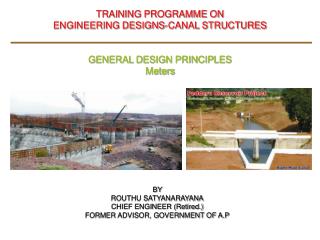
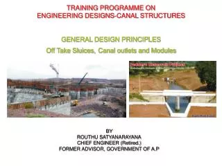
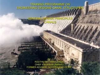
TRAINING PROGRAMME ON ENGINEERING DESIGNS-CANAL STRUCTURES GENERAL DESIGN PRINCIPLES CANALS & CANAL LINGING. BY ROUTHU SATYANARAYANA FORMER CHIEF ENGINEER FORMER ADVISOR, GOVERNMENT OF A.P. Canal & Design Principles.

E N D
TRAINING PROGRAMME ON ENGINEERING DESIGNS-CANAL STRUCTURES GENERAL DESIGN PRINCIPLES CANALS & CANAL LINGING BY ROUTHU SATYANARAYANAFORMERCHIEF ENGINEER FORMER ADVISOR, GOVERNMENT OF A.P
Canal & Design Principles • Definition: A canal is an artificial channel, trapezoidal in shape to carry water to the field from a source, such as a reservoir, river or a tank. • The motive force in the flow of an open channel is the slope of the water surface • The water flows from higher level to lower level by virtue of gravity. • The resistance in the canal are surface tension, atmospheric pressure, surface friction at the bottom and sides.
Canal & Design Principles • Canal Alignment: • The canal has to be aligned in such a way that it covers the entire area proposed to be irrigated with the shortest possible length and at the same time its cost includes the cost of Cross Drainage and Cross Masonry works and they are the minimum. • A shorter length ensures less loss of head due to friction and smaller loss of discharge due to seepage and evaporation.
Canals & Design Principles • Classification of Canals based on • Canal excavation in Soils: • Alluvial Canals and Non- alluvial Canals • Functions of the Canal: • Irrigation Canal -Carrier Canal Feeder canal – Navigation Canal – Power Canal • Shape of channel: • Circular, Rectangular, Trapezoidal, Triangular, Parabolic • Canal alignment: • Contour Canals - Ridge Canals or water shed canals – Side Slope Canals. • Discharge and Importance: • Main Canal-Branch Canal-Major and Minor Distributaries-Water course. • Nature of the Canal: • Un-lined canal-Lined canal.
Canals & Design Principles • Design parameters: • Discharge: • The discharge capacity of the canal is the maximum discharge required for the ayacut for the given duty and the losses in the system. • It shall be fixed based on, • The cultivable command area, • Water allowance, i.e. the outlet capacity in cumecs/s per thousand hectares considering the duty, intensity, proposed crop ratio, water availability, etc; and • Transmission losses due to seepage and evaporation from canals water courses and irrigated area. • The carrying capacities of the canals and distributaries have to be worked out from head to tail.
Canals & Design Principles • Design parameters: • Best Discharging Channel is that which for the same Cross Section and slope, passes water with the maximum velocity and the maximum hydraulic mean radius (R=A/P), and with the smallest absorption losses commensurate with economy. • The canal has to be aligned in such a way that it covers the entire area proposed to be irrigated with the shortest possible length and at the same time its cost includes the cost of Cross Drainage and Cross Masonry works and they are the minimum.
Canals & Design Principles • Design parameters: • The common procedure is to determine the Width (W) and Depth (D) of a canal for a given discharge (Q), coefficient of rugosity, side slopes, surface fall or bed gradient, and minimum and maximum velocity. The formula for determine the discharge capacity of the canal. Discharge (Q) = A (area ) x V ( Velocity) • The Cross section of the canal will be in • Full cutting • Full banking or • Partial cutting and Partial banking
Canals & Design Principles • Discharge Formula for open head channel : Discharge (Q) in cumecs = AxV where , A= Cross sectional area in Sq.m V= Mean velocity of flow in m/s Velocity is computed using Manning’s formula V= (R2/3S1/2)/n where, R= Hydraulic mean radius (A/P) in m S=Surface Slope of water/bed slope P= Wetted perimeter in m n= Coefficient of rugosity.
Canals & Design Principles • Design parameters: • Coefficient of rugosity ’n’: To over come surface tension friction on sides and bottom of the canal. ______________________________________________________________ Canal Un-lined canal Lined canal ______________________________________________________________ Alluvium 0.0225 to 0.025 Gravel 0.025 Natural drains 0.03 to 0.035 Concrete lining 0.018 to 0.020 Shot Crete finish 0.018 to 0.022 • Free Board: Measured from FSL/HFL to top of bund or top of lining _____________________________________________________________________
Canals & Design Principles • Design parameters : • Free Board: Measured from FSL/HFL to top of bund or top of lining __________________________________________________________________ Canal discharge lined canal in Cumecs in mm ___________________________________________________________ < 0.10 150 < 1.00 300 1.00-3.00 500 3.00- 10.00 600 >10.00 750 _____________________________________________________________ For unlined canals , minimum free board=500mm up to Q,<10cumecs and 750mm for Q.10 cumecs.
Canals & Design Principles • Design parameters: • Bank Top widths: For distributaries <3 cumecs discharge formation of service road may not be necessary, but only land widths ay be provided on the natural ground _____________________________________________________________________ Canal discharge UN-lined canal in m Lined canal in m in Cumecs Inspection Non inspt. Insp. Non-Insp. ______________________________________________________________________ 0.15-1.50 5.00 1.50 4.00 1.50 1.50-3.00 5.00 1.50 4.00 2.00 3.00-7.50 5.00 1.50 4+dowel 2.50 7.50-10.00 5.00 2.50 4+dowel 2.50 10.00-10.50 6.00 2.50 4+dowel 2.50 10.50-15.00 6.00 2.50 5+dowel 4.00 15.00-30.00 7.00 3.50 5+dowel 4.00 > 30.00 ---- ----- 6.+dowel 5.00 ___________________________________________________________________________ Dowel Banks: To protect the inner slops from rain water • Main canal and Branches: 500mm top width, 500mm high with 1.5:1 slops on either side • Distributaries: 300mm top width and 300 mm high.
Canals & Design Principles • Design parameters: • Inner slopes of the canal: To safe guard against sudden draw down condition. ----------------------------------------------------------------------------------------------------------------------- Type of soil Side slopes, Horizontal to vertical in embankment in cutting ----------------------------------------------------------------------------------------------------------------------- All soils 2:1 1.50:1 Rock - Disintegrated Rock … 1.00:1 HDR … 0.50:1 Hard Rock … 0.25:1 ----------------------------------------------------------------------------------------------------------------------- • B/D Ratio: __________________________________________________________________________ Discharge in Cumecs B/D Ratio __________________________________________________________________________ 0.05 to 0.50 1.0 to 1.50 0.50 to 5.00 1.5 to 2.00 5.00 to 50.00 3.5 to 6.00 50 to 200 6.00 to 8.00 Above 200 8.00 to 10.00 __________________________________________________________________________
Canals & Design Principles • Design parameters: • Mean Velocity: _________________________________________________________________________ Soil Mean Velocity in m/s __________________________________________________________________________ All soils 0.6 to 1.1 Gravel 1.5 to 1.8 Rock 1.4 to 2.7 Hard rock 4.5 to 7.6 Stone Masonry 3.00 Concrete < M30 4.00 > M30 6.00 Steel and Cast Iron 10.00 ________________________________________________________________________ * Mean Velocity of 1.5 to 2 m/s even up to 2.7 m/sis desirable for lined canals
Canals & Design Principles • Radius of curvature : as per IS: 5968-1987 and IS: 10430-2000 RADII OF CURVES FOR CANALS As per table 1.of IS; 5968 – 1968 Reaffirmed 2003) ----------------------------------------------------------------------------------------------------------------------------------------------------------------------- Un lined canals Lined canals --------------------------------------------------------------------------------------------------------------------------------------------------------------- Discharge Radius Discharge Radius In cumecs in m in cumecs in m _____________________________________________________________________________________________________ 80 and above 1500 280 and above 900 80 to 30 1000 280 to 200 750 30 to 15 600 200 to 140 600 15 to 3 300 140 to 70 450 3.0 to 0.3 150 70 to 40 300 Less than 0.3 90 40 to 10 00 • 10 to 3 150 3.0 to 0.3 100 Less than 0.3 50 Note 1. The above radii are not applicable to un-lined canals located in hilly reaches and highly permeable soils. 2. On lined canals where the above radii may not be provided proper super elevation shall be provided. _____________________________________________________________________________________________________
Canals & Design Principles • TRANSMISSION LOSSES: • The losses take place in account of evaporation and seepage. • These losses are quite considerable and accounts roughly 25 to 50 percent of canal discharge in unlined canals. • The seepage losses are influenced by the nature and porosity of the soils, the depth turbidity and the temperature of the water. • The age and the shape of the canal and the ground water table etc; • Seepage losses dependent on nature and permeability of soil, depth of water in the canal and the sub soil water table. • Generally canal reaches having permeability 10-5cm/s or less need not be lined. • In case of lined canals, seepage losses may be assumed as 0.60 cumecs/million square meters of wetted perimeter.
Canals & Design Principles • SEEPAGE LOSSES IN UNLINED CANALS (As per table 2 of Manual on Irrigation and Power Publication no.171 by CWC) -------------------------------------------------------------------------------------------------------------------- Character of material Seepage loss in Cumecs per Million sq. m of wetted perimeter _____________________________________________________________________ Impervious clay Loam 0.90 to 1.20 Medium clay loam under laid with hard pan at depth 1.20 to 1.80 of not over 0.60 to 0.90m below level Ordinary clay loam silt soil or lavash loam 1.80 to 2.70 Gravelly or sandy clay loam, cemented gravel, 2.70 to 3.70 Sand and clay Sandy loam 3.60 to 5.20 Loose sandy soils 5.20 to 6.10 Gravelly to sandy soils 7.00 to 8.80 Porous gravelly soil 8.80 to 10.70 Very gravelly soils 10.70 to 21.30 Note: In the case of lined canals, seepage losses may be assumed as 0.6. Cumecs per million square meters of wetted perimeter. ___________________________________________________________________
Canals & Canal Lining • Lining of canal : • It is an important feature, as it improves the flow characteristics and minimizes the loss of water due to seepage. • The water thus saved can be utilized for the extension and improvement of the irrigation. • Lining assumes special significance in pumped water supply as the water is relatively costly. • Studies indicate that seepage losses in irrigation channels constitute 25 to 50 percent. Generally canal reaches having permeability of 1x10⁻³ cm/s and more may be lined. • Experiments in south India it is found that cement concrete lining has a rate of seepage of only about 0.50 cusec per million square feet against 8.0 cusecs in an unlined canal. • For the purpose of economic analysis, the life expectancy of concrete, brick/ tile and stone pitched lining may be assumed to be of the order of 60 years.(IS:10430-2000)
Canals & Canal Lining • Advantages of lining: • Seepage control. • Prevention of water logging. • Increased hydraulic efficiency. • Increased resistance to erosion/abrasion. • Reduction in cross sectional area. • Low operation and maintenance cost. • Prevention of weed growth. • Elimination of siltation due to permissible higher velocity. • Resistance against burrowing animals. • Cement concrete in-situ lining is the most conventional type of lining. • Higher velocity up to 2.7 m/s can be permitted. • It eliminates weed growth, resistance against burrowing animals, and improves flow characteristics and low maintenance costs. • A distinct disadvantage is its lack of extensibility, which result in frequent cracks due to contraction, shrinkage and settlement of sub grade.
Canals & Canal Lining • Specifications: • The provisions in the relevant Indian Standards are to be followed in Toto in the case of CC lining for main canals, branch canals and larger distributaries having bed width of more than 10m (for canals with sub-strata of non-expansive soils) and or discharge of more than 10 cumecs. In the case of smaller size distributaries, the recommendations of the Expert Committee on Nagarjunasagar Project Main canals and Branch canals are being followed.
Canals & Canal Lining • Thickness of In-Situ lining ___________________________________________________________ Capacity of canal depth of water Thickness of lining in cumecs. in m in mm (minimum) ___________________________________________________________ 0 - 5 0 – 1 50 – 60 5 - 50 1 – 2.5 60 – 75 50 – 200 2.5 – 4.5 75 – 100 200 – 300 4.5 – 6.5 90 – 100 300 – 700 6.5 – 9.0 120 – 150 ___________________________________________________________ • Expert Committee recommended thickness for Distributaries ___________________________________________________________ 0 - 5 60 5 - 50 75 -----------------------------------------------------------------------------------------------
Canals & Canal Lining • Coping for lined canals: • To check the ingress of rainwater behind the lining of the side slopes of the canals, horizontal cement concrete coping 100m to 150mm, depending upon the size of the canal should be provided at the top of the lining. • The width of the coping at the top shall be: ______________________________________________________________ Discharge Width -------------------------------------------------------------------------------------------- i). up to 3.00 cumecs 225mm ii) 3 to 10 cumecs 350mm iii). Above 10 cumecs 550mm. ----------------------------------------------------------------------------------------------- • A parapet wall may replace a dowel. However, the height of the parapet should not be considered additional free board. • BERMS: • Berms are to be provided in all cuttings when the depths of cutting are more than 5m. It is desirable to provide berms of three to 5meters at every 5m depth intervals on each slide for stability and maintenance.
Canals & Canal Lining • Cross Section of the Lined Canal: • As per Cl. 8.8.1 of IS 10430: 2000, The cross section of the lined canal may be trapezoidal with or without rounded corners, and the figure referred there in , shows: • Bed lining and side lining to be joined with circular curve of radius equal to full supply depth of the canal. • The Radius of Curvature ( R ) adopted in the case of IndiraSagarPolavaram Project, and Sardharsarovar Project Canals is1500mm. • The Expert Committee on NSP , in a Specific case recommended the radius of curvature (R) equal to 1500mm.
UNDER-DRAINAGE - LINED CANALS • Suitable under drainage should be provided to protect the lining, where the canal crosses an area subjected to seasonal high ground water. • Excessive hydrostatic pressure sufficient to damage the lining when the canal is empty or canal is low water level. • Drainage arrangements provided mainly depend s up on the position of the water table and the type of sub grade. • Water table may be: • Below canal bed level • Between canal bed level and full supply level • Above canal full supply level • The sub grade may be • Free Drainage • Poor Drainage • Practically Impervious
UNDER-DRAINAGE - LINED CANALS • Necessity of Drainage and Filters below lining: • Water table below CBL: A ). Sub grade free drainage • No drainage arrangements required, and no pressure relief arrangements required B ). sub grade poor drainage • Provide 150 to 200mm filters and pressure relief arrangements with longitudinal and transverse drains with PRVs in the bed, PRVs in the pockets filled with filters in the sides. C ). Sub grade impervious • Sub grade to a depth of 600mm to be removed and refilled with sand, murram or suitable pervious material and pressure relief arrangements as above required.
UNDER-DRAINAGE - LINED CANALS • Necessity of Drainage and Filters below lining 2. Water table between CBL and FSL: a). Sub grade free drainage • provide 150 to 200mm filters and pressure relief arrangements with Longitudinal and Transverse drains I with PRVs in the bed and PRVs in pockets filled with filters in the sides. b). Sub grade poor drainage • Provide 200 to 300mm filters and pressure relief arrangements as above c). Sub grade impervious • sub grade to a depth of 600mm to be remove and refilled with sand, murram, or suitable pervious material. Pressure relief arrangements in bed and sides as above are required.
UNDER-DRAINAGE OF LINED CANALS • Necessity of Drainage and Filters below lining 3. Water table above FSL a). Sub grade free drainage • provide150 to 200mm filters b). Sub grade poor drainage • Provide 200 to 300mm filters c). Sub Grade impervious • Remove the sub grade to a depth of 600mm and back filled with sand, murram, or suitable pervious material • Pressure relief arrangements • Bed – Longitudinal and Transverse drains with PRVS • Sides- Transverse drains with PRVs • Longitudinal drains: • Trapezoidal with bottom width 500mm,and depth 525mm. Number depending on the bed width of the canal usually at least one drain for every 10m width.
UNDER-DRAINAGE OF LINED CANALS • Transverse drains: • Provided in the bed and on the side slopes up to free board level • Provided at 10m intervals • Pressure Relief Valves (PRV) • Provided on the longitudinal/Transverse drains • Spacing, one row at every 4m on the sides, the first row 50cm above curve line and top row 50 t0100mm below FSL. If the depth of water is less than 1.5m, one row will be adequate. • Spacing one PRV for every 100 sq.m in the canal bed and one for every 40 sq.m for sides • Porous concrete Plugs : • Size 100mm dia. And 400mm long may be provided in place of PRVs
Canals & Canal Lining • Over excavation: • For slopes more than 1:1 in hard strata: • Backfilled with gravel and aggregate and a layer of pea gravel as binding material. • The bed may be compacted with road roller and the sides with rammers. • For slopes less than 1:1 in hard strata : • Back fill shall be chip masonry, Alternatively, lean concrete. • Sleepers/profile walls: • At intervals of 20m/17.5m in straight reaches and 10m /8.75 in curves. The size shall be 250mm wide and 150mm deep built in the same grade of lining, for the main & branch canals and larger distributaries and 200mm X 150mm for other distributaries. • Sleeper shall be placed centrally under the joints. (Cl.5.5.1.1.5 of IS 3873-1993) • Expansion Joints: • These should not be provided except where a structure intersects is the canal. The Thickness of Expansion shall be 12mm. • Construction Joint: • Joints are potential points of seepage. A construction joint is weak link in the lining and deterioration starts from such joints. • As such, number of joints shall be kept minimum. • Dowel Banks: • Main canal & branch canal: 500mm top width, 500mm high with side slopes 1.5:1 • Distributaries' : 300m top width, 300mm high with side slopes 1’5:1
Canal lining • Contraction joints • Contraction joints should be provided in canal lining at interval of not more than 36 times the thickness of lining, in both longitudinal and transverse directions. The following spacing is adopted for different thicknesses of lining. Thickness of lining(mm) Spacing of contraction joints(mm) 60 2000 75 2500 100 3500 120 4000 • Where in-situ CC lining is laid with mechanical pavers, PVC strips should be provided in the contraction joints. The size of the PVC strips for the longitudinal and transverse contractions joints are shown . • Where alternate method of contraction joints is adopted by cutting the groove in the lining concrete and filling with sealing compound, the dimensions of the groove should be as per the figure shown.
Canals & Canal LiningConventional Groove – Contraction Joint
Canal lining • Construction joints • The construction joints are provided in the canal lining, wherever there is discontinuity of concrete work for a period of time leading to creation of cold joint. Generally bed lining is executed in advance of the laying side lining. As such construction joints are required on either side of canal bed at the junction of bed and side lining. Normally longitudinal construction joints are provided at about 500 to 1000 mm from the tangent point of the curve at the junction of canal bed and the side slope on either side of the bed. In the case of small channels, where bed and side lining are laid simultaneously, longitudinal construction joints are not provided. Transverse construction joints should be provided, where discontinuity of work for considerable time is expected. 200 mm x 150 mm size CC M15 grade sleepers are provided under the construction joints. The joint should be filled with hot pour sealing compound as per specifications in IS: 5256 – 1992. • Steps • 1500mm wide (minimum) steps in CC M15 grade should be provided at 300 m C/C staggered on either side of the canal as stipulated in IS: 3873 – 1993. 3000 mm wide steps are to be provided at the villages and structure locations. In the case of smaller distributaries, steps are to be provided arbitrarily as per the certificate of the Executive Engineer.
Canals and Canal LiningDetails of construction and contraction Joints
Sealing Compound for Grooves – Canal Lining SPECIFICATIONS OF SEALING COMPOUND FOR FILLING LONGITUDINAL AND TRANSVERSE CONTRACTION JOINT GROOVES: The sealant is prepared from the materials as under: (i) Bitumen 85/25 . . . . . . . . . . . . . . . .. . . . . . . . . . 55% (ii) Sand (fineness modulus 1.0 to 1.5)…………….. 43% (iii) Asbestos powder . . . . . . . . . . . . . . . . . . . . . 2% Bitumen: The Bitumen 85/25 shall be tested as per IS code 702-1961 prior to its use.
Canals & Canal Lining • Lining of Canals in Expansive Soils: • Canals excavated in expansive soils, such as black cotton soils, pose several problems, • Involving stability of slopes and shape of section. • Cast in situ lining for bed and pre cost cement concrete slabs for sides are common. • The lining material directly placed against expansive soils under go deformation by heaving, disturbing the lining . • This deformation is due to unduly high pressure developed by the expansive soils when they absorb water. • By protecting the soil, the heaving of the soil mass is contained mass with a thin layer of muram gravel. • To counter the swelling pressure and prevent deformation of the rigid lining material a cohesive Non-swelling (CNS) layer of suitable thickness depending on the swell pressure of the expansive soil is sand- witched between the soils and the rigid lining material.
CNS Soils – Canal lining • Treatment of sub-grade • The soils with swelling pressures of more than 50 kN/m2 are classified as expansive soils. Expansive soils sub-grade should be covered by a layer of CNS (cohesive non-swelling soil) material of sufficient thickness before laying the canal lining. • Properties of CNS Material : • The CNS soils are to be non-swelling soils with a maximum allowable swelling pressure of 10 KN/m2 when tested in accordance with IS 2720 (Part 41): 1977. CNS soils should broadly confirm to the following range: Clay (Less than 2 microns) . . . . . . . . . . . . 15-20% Silt (0.06 mm - 0.002 mm) . . . . . . . . . . . . . 30-40% Sand (2mm - 0.06 mm) . . . . . . . . .. . . . . . . 30-40% Gravel (of size greater than 2mm) . . . . . . 0-10% Liquid limit . . . . . . . . . .. . . . . . . . . . . . . . . More than 30 but less than 50% Plasticity Index . . . . . . . . . . . . . . . . . . . . . . More than 15 but less than 30% • The extent of provision of CNS for the treatment of sub grade, has been determined through testing of soil samples for the swelling pressures.
CNS Soils – Canal lining • Treatment of sub-grade • Thickness of CNS layer • The thickness of CNS layer is related to the swelling pressure of the expansive soil and the resultant deformation, the permissible deformation being 2 cm. The thickness of CNS layer required for balancing different swelling pressures of the expansive soils shall be as per the following table: • Canal carrying capacity less than 2 cumecs Min. thickness of CNS layer (cm) Discharge(Cumecs) Swelling pressure 50 – 150 kN/m2 Swelling pressure more than 150 kN/m2 1.40 – 2.0 60 75 0.70 – 1.40 50 60 0.30 – 0.70 40 50 0.03 – 0.30 30 40 • Canal capacity of 2 cumecs and more welling pressure of soil kN/m2 Thickness of CNS layer cm (min) 50 – 150 75 150 – 300 85 300 – 500 100 • Note: Optimum thickness of CNS materials needs to be determined for different swelling pressures by actual experiments both in field and in laboratory, if necessary.
Canals & canal liningBottom Rail and Drainage for Expansive Soils
Canals & Canal Lining • Canal lining in rock strata • The requirements for the canal lining in the rock strata shall be same as for lining in soil strata except for the under-drainage arrangements. 300 mm ф porous concrete blocks with thickness equal to the lining thickness are provided in the centre of each lining panel in the bed. The number of porous concrete blocks is increased according to necessity. For the canal side lining normal method is followed, where the soil strata exist. In the case of deep cuts with steep side slopes, shot Creting is adopted for the side lining and for drainage arrangement, perforated PVC pipes are provided in two rows, with the pipes in the rows staggered and the distance between the pipes in each row shall be 70 m. Additional number of pipes shall be provided where necessary.
Canals & Canal Lining • Shot Crete lining: (IS: 9012- 1978). • Shot Crete is a type of lining, wherein cement motor/ cement concrete is applied to the surface by pneumatic pressure with or without reinforcement. • Shot Crete lining can be easily placed over rough sub grade and therefore, better suited for use on deep cut reaches. • The thickness of the lining limited to 5.0 cms mostly. • Stone pitched lining (IS 4515: 2002) • Stone pitched lining will be useful in the following cases. • Prevention of erosion • Where the ground water level is above the bed of the canal, this type of lining will allows water pressure to be released through the interstices.