Download
1 / 40
430 likes | 663 Views
TRAINING PROGRAMME ON ENGINEERING DESIGNS-CANAL STRUCTURES GENERAL DESIGN PRINCIPLES Meters. BY ROUTHU SATYANARAYANA CHIEF ENGINEER (Retired.) FORMER ADVISOR, GOVERNMENT OF A.P. Communications-Bridges. Definition:

E N D
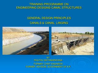
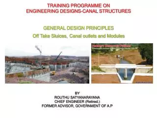
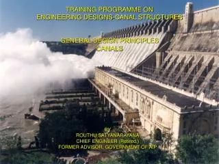
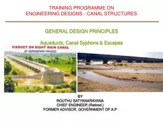
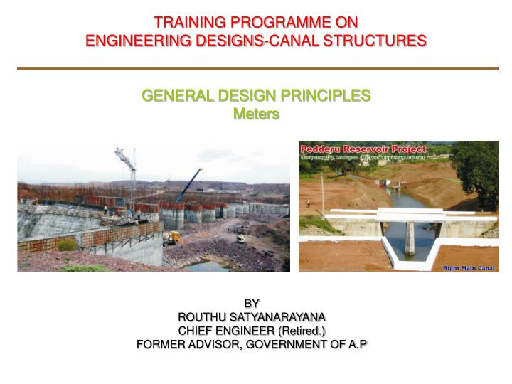
TRAINING PROGRAMME ON ENGINEERING DESIGNS-CANAL STRUCTURES GENERAL DESIGN PRINCIPLES Meters BY ROUTHU SATYANARAYANACHIEF ENGINEER (Retired.)FORMER ADVISOR, GOVERNMENT OF A.P
Communications-Bridges • Definition: • Bridge: A Structure having a total length above 6m between the inner faces of the dirt walls for carrying traffic or other moving loads over a depression, a obstruction such as a channel, road or a railway. • Minor Bridges: A bridge having a total length of 60m. • Major bridges: A bridge having a total length more than 60m. • Culvert: A structure having a total length less than 6m between the inner faces of the dirt walls. • Foot bridge: A bridge exclusively used to carry pedestrians, cycles and animals. width shall not be less than 1500mm. • High Level Bridge: A bridge which carries the road way above the HFL of a channel. • Submersible bridge: A submersible bridge or vented causeway is a bridge designed to be overtopping during floods.
Communications-Bridges • Width of carriage way: The minimum clear width measured at right angles to the longitudinal centre line of the bridge between the inside faces of roadway kerbs of wheel guards. • Width of footway: The minimum clear width any where within a height of 225mm above the surface the footway or safety kerb. Normally 1.5 m from outer rounding of kerb to inner fce of the parapet/railing. • Safety Kerb: A road way for usage of pedestrians. High Level Bridge: A bridge which carries the road way above the HFL of a channel. • Super elevation: Transverse inclination given to the cross section of a carriageway on a horizontal curve in order to reduce the effect of centrifugal force on a moving vehicle. • Crust level of the bridge: It shall be the highest of the following: • Road crust level • TBL of the canal • Ground level
Communications-Bridges • Submersible bridges and vented Causeways: Railing shall be either collapsible or removable. • Crash Barriers: Suitable designed crash barriers provided to safe guard against errant vehicles. Metal or RCC. • Multilane bridges and bridges on a urban area • Flyover and interchanges • ROBs across railway line • Open sea, breakwaters, deep valleys • Types: • Vehicle cross barriers. • Combination Railway/Vehicle Pedestrian Crash Barriers • High Containment Barriers
Communications-Bridges • Approaches to bridge Minimum straight length of 15m on either side and width equal to the carriage width. • Bearings: • Expansion Joints • Foundations:
Communications-Bridges • Basic Data: • Site plan with contours showing the flow direction of the canal, road way angle (direction of skew if any), and the approach of the road for 200m on either side. • Names of the village/town connected on either side. • Hydraulic particulars of the canal both upstream and downstream. • LS of the canal and the road for at least 250 m on either side of crossing. • Cross sections of the canal and the road duly marking, Levels, such as BL, FSL, TBL, GL, road crust level etc., • TPs Particulars, taken up to hard strata or to a minimum depth of 2m below CBL or ground level which ever deeper with soil classification. • Bearing capacity of the foundation strata.
Communications-Bridges • Design Criteria: • Hydrology of the drain or stream. • Hydraulic design of • The stream or drain • The hydraulic deign of the canal • Structural Design. • Super structure • Sub structure References: IRC: 5-1998, 6-2000, 21-2000,78-2000, 83 (Part-1)-1987,
Communications-Bridges • Design Criteria: • Hydraulic design of • Design of vent way • Bridge crust level • Afflux by Molesworth’s formula (max.50mm). • Check for Scour • Structural Design: • Super structure • Substructure. References: IRC: 5-1998, 6-2000, 21-2000,78-2000, 83 (Part-1)-1987,
Bridges-Hydrology • Hydrology of the stream or drain: Table-1 Category Canal Discharge Stream DischargeFlood Frequency in cumecs in cumecs A 0.0 - 0.5 All discharges 1 in 25 years B 0.5 – 15 0 – 150 1 in 50 years Above 1501 in 100 years C 15 – 300 – 100 1 in 50 years Above 1501 in 100 yeas DAbove 300 - 150 1 in 100 years Above 150Detailed study • IS: 7784 (part-1)-1973.
Communications-Bridges Hydrology of the Drain/Stream: Detailed study in the case of drain discharge > 150 cumecs and canal discharge > 30 cumecs. S.No. Type of Canal Catchment Area (CA) in ‘M’ in Sq. Miles Up land Areas Deltaic Tracts 1. Main Canal Dickens’s formula, Rye's formula Q = CM 3/4 Q = CM 2/3 C=1400 for CA<1.00C=1000 C=1200 for CA=1 to 30Velocity shall not exceed 10 ft/sec C=1060 for CA=30 to 500 Q=7000 M1/2 for CA>500 Velocity in the barrel up to 12 to13 ft/sec 2. Branch CanalQ=CM 2/3 Q > 500 c/s C=1000 and Velocity<10’/sec same as upland area 3. Distributaries Q = CM 2/3 same as upland area Q < 500 c/s C=750 and Velocity< 10”/sec • Lr. No. CDO/EE-C1/1084/83-3 dated 23.08.1983.
Bridges-Hydrology • Hydrology of the stream or drain: Table-1 Category Canal Discharge Stream Discharge Flood Frequency in cumecs in cumecs A 0.0 - 0.5 All discharges1 in 25 years B0.5 – 15 0 – 150 1 in 50 years Above 1501 in 100 years C 15 – 30 0 – 1001 in 50 years Above 1501 in 100 yeas D Above 30 0 - 150 1 in 100 years Above 150Detailed study • IS: 7784 (part-1)-1973.
Bridges-Hydraulic design • Linear Waterway: Width of the water way between the extreme edges of water surface at the highest flood level measured at right angle to the abutment faces. Layce’s wetted perimeter (Pw) in meters using the formula Pw = C(Q)1/2 Where C = a coefficient, a value 4.8 (4.5-6.3)and Q is the flood discharge in cumecs • Effective linear waterway: Total width of the waterway at HFL minus the effective width of the obstruction. • Length of the bridge: Over all length measured along the centre lline of the bridge between inner faces of dirt walls.
Bridges-Hydraulic design • Vertical Clearance: • It is the vertical distance measured from HFL or FSL including the afflux o the underside of deck of the structure.. S. No. Designed flood in CumecsMinimum Vertical Clearance in mm 1. < 0.3150 2 Between 0. 3 and 3.0450 3. Between 3.0 and 30 600 4. Between 30 and 300 900 5. Between 300 and 3000 1200 6. > 3000 1500
Bridges-Hydraulic design • Vertical Clearance: • No part of the bearings shall be at a height less than 500mm • Vertical clearance above the roadway in any traffic lane up to the lowest point 5.5 • Free board: • It shall not be less than 750mm for approaches to high level bridges. • Scour Depth: • Mean scour depth is the depth (dm) below HFL or FSL in m d = 1.34[q2 /f]1/3 Where, q = Discharge per meter width with or without concentration of flow in cumecs, f = Layce’s silt factor expressed as f = 1.76 (d m )1/2 dm = average grain size
Bridges-Hydraulic design Bed material Weighted mean diameter Value of silt of particle in mm-dmfactor- f Coarse silt 0.040 0.350 Fine silt 0.081 0.500 Fine silt 0.120 0.600 Fine silt 0.158 0.700 Medium silt 0.233 0.850 Standard silt 0.323 1.000 Medium sand 0.505 1.250 Coarse sand 0.725 1.500 Fine bajira & sand 0.988 1.750 Heavy sand 1.290 -2.00 2.000 – 2.42
Bridges-Hydraulic design • Maximum Scour depth or Designed Scour Depth 9dorR) in m: • Straight reaches for individual foundations without floor protection In the vicinity of pier 2.00 d Near abutments 1.27 d approaches retained 2.00 d scour all round Floods with seismic combinations the values may be reduced by 0.9 For floor protection works, for raft foundations and shallow foundations In straight reaches 1.27 d At moderate bends 1.50 d At sever bends 1.75 d m At right angle bends 2.00 d • Depth of Foundation: • In Soils Up to safe bearing capacity or a minimum of 2.0m below the scour level or the protected bed level. • Hard rock with crushing strength 10 MPA: 600mm • All others : 1500mm
Bridges-Hydraulic design • Well foundation: • Maximum scour depth plus a 1/3 grip length • In rock a minimum shear key: 300mm in hard rock 600mm in soft rock • Sump (Shear Key) diameter 1.5m to 2.0m less than inner hole, anchored 1.5m below with six dowel bars of diameter 25mm places in 65mm grout hole and projected 1.5m above
Bridges – Structural design • Loading Classification • IRC Class AA Loading or Class 70-R Loading • IRC Class A Loading • IRC Class B Loading – adopted for temporary structures only • Loads, Forces and Stresses: 1. Dead Loads 2. Live Loads 3. Snow loads 4. Impact and Dynamic Loads 5. Vehicle collusion load 6. wind load 7.Impact due to floating bodies 8. Water currents 9. Breaking force 10. Centrifugal forces 11. Buoyancy 12. Temperature effects 13. Deformation effects 14. Secondary effects 15.Errection effects 16. Seismic force 17. Wave pressure 19. Grade effects 19. Earth Pressure & LL surcharge
Bridges – Loads, Forces,& Stresses • Loads, Forces and Stresses: • For Class A or Class B Loading for spans (L) in m between 3m and 45m • For RCC bridges = 4.5/(6+L) • For Steel bridges + 9.00/(13.5+L) • For Class AA Loading and Class 70R Loading • Spans < 9m Tracked Vehicle: 25% for spans up to 5m linearly reducing to 10% for spans 9m Wheeled vehicles:25% • Spans of 9m and more Tracked vehicles: 10% up to spans 40m and in accordance with curves for span > 40m Wheeled vehicles: 25% for spans up to 12m and in accordance with curves for span >12m • Steel bridges: • Tracked vehicles: 10% for all sans • Wheeled vehicles: 25% for spans up to 23m and in accordance with curves for span > 23m
Bridges – Structural design • Loads, Forces and Stresses: Impact: • No impact allowance is added for footway bridges • If the earth filling is > 600mm including the road crust the impact shall be reduced to 50%. • For Pressure on Bearings and top of Bed Blocks it shall be 100% • Pressure at Bottom surface of the Bed Block- 50% • Pressure on the top 3m of the structure below the bed block – 50% decrease to Zero at bottom • Pressure on the portion of the structure > 3m below bed block - Zero
Bridges – Structural design • Loads, Forces and Stresses: • Wind Load: Horizontal force: • For deck- area as seen in elevation including floor and railing, less area of perforation in the hand railing • For through or half trough structures- The area of elevation of the wind ward truss as specified as above plus half the area of elevation above he deck level of all other trusses or girders. The intensity of wind force based on wind pressure and wind velocity. • It shall be doubled for Guntur, Krihna, Godavri, Visakha, Vijayanagaram and Srikakulam districts along the coast line
Bridges – Structural design Wind Pressure and Wind Velocity H V P H P V 0 80 40 30 147 141 2 91 52 40 155 157 4 100 63 50 162 171 6 107 73 60 168 183 8 113 82 70 173 193 10 118 91 80 177 202 15 128 107 90 180 210 20 136 119 100 183 217 25 142 130 110 186 224 Where W=Average height in m of the exposed suface above ground, bed level or water level V= Horizontal velocity f wind in Km per our at height H P= Horizontal wing pressure in Kg/Sq.m at height H (con….)
Bridges – Structural Design • Wind Load: • The lateral wind force against any exposed moving live load as acting 1.5m above road way and shall be assumed to have the following value. • Highway bridges , ordinary : 300 Kgs/linear meter • Highway bridge carrying tramway: 450 Kgs/linear meter • The bridge no carrying any live load when the wind velocity at deck level exceeds 130 Kms per hour. • The total assumed wind forces as calculated in accordance above cl.1 to 4, shall however , not less than 450 Kg per linear meter in plane of the load chord and 225 Kg per liner meter in the plane of unloaded chord on through or half through truss, lattice or other similar spans, and not les than 450 Kg per linear meter on deck slab. • A wind pressure f 240 Kg/Sqm on the unloaded structure, applied as specified in cl1, 2, shall be used if it produces greater stresses than those produced by the combined wind forces as peer cl. 1, 2,4 or by the wind force as per cl.5
Bridges – Loads, Forces,& Stresses • Horizontal Forces Due to Water Currents: • On piers parallel to the direction of the water current, the intensity of pressure shall be as follows: P = 52 KV2 Where P= Intensity of pressure due to water currents in kg/m V= Velocity of the current at the point in m/s (Maximum velocity) K= a constant depending on shapes of pier as under Square ended ; 1.5 circular pier or with semi circular ends: 0.66 Triangular cut and ease waters: 0.50 The value of V2 assumed to vary linearly from zero at the point of deepest scour to the square of the maximum velocity at the free surface of water. Maximum velocity = 1.414 times he maximum mean velocity
Bridges – Loads, Forces,& Stresses When the current strikes the pier at an angel it resolved in totwo components. 1.Presur parallel to pier- as above 2. Normal to the pier, acting on the area of the side elevation of the pier- as with K as 1.5, except for circular piers which shall be 0.66. Possible variation of water current direction inclined at (20±Ə) to length of pier Bridge having pucca floor static force due to difference in head of 250mm between the two faces of the pier.
Bridges – Loads, Forces,& Stresses • Longitudinal Forces: • Force arising from any one or more of the flowing: • Tractate force due to acceleration • Breaking effect (invariably greater than tractate force) • Frictional resistance offered by the free bearings due to temperature change. • The Breaking effect: • In the case of single lane or two lane bridges: • 20% of first train load plus 10% of the succeeding train or part thereof on one lane only • If the entire train is not on the full span, breaking force shall be 20% of the loads actually on the span, ii In the case of more than two lanes: • As in ‘A’ above for the first two lanes plus 5% of the loads on the lane in excess of two. • The force due to breaking effect acting at 1.2 m above parallel to road way.
Bridges – Loads, Forces,& Stresses • The change in vertical reaction at the bearings to be accounted for. • Simply supported spans on unyielding supports: • For spans of fixed and fee bearing other than Elastomeric bearings, longitudinal forces Fixed bearing Free bearing (i). Fh-µ(Rq+Rg) µ(Rq+Rg) Or (ii). Fh/2 + µ(Rg+Rq) µ(Rg+Rq) Where Fh= Applied horizontal force Rg= Reaction due to dead load at free end Rq= Reaction due to live load at fee end µ = a coefficient For steel roller bearings 0.03 concrete roller bearings 0.05 sliding bearings 0.30 to 0.50 Teflon on stainless steel 0.03 to 0.05 • Plate bearings up to 15m span for RCC or Pre stressed super structure. :
Bridges – Loads, Forces,& Stresses • Simply supported spans on unyielding supports: • For spans up to 10 m where no bearings are provided , the longiudilnal forces at bearing level shall be Fh/2 or µ Rg • Elastomeric bearings: Longitudinal force= Fh/2+Vr Lu Where Vr= shear rating of the Elastomeric bearing Lu= movement of deck above bearing • The sub structure and foundation shall also be designed for 10% variation in movement of the span on either side.
Bridges – Loads, Forces,& Stresses • Centrifugal Forces: • Determined from the following formula: C = W V2/ 127 R Where C= Centrifugal force in tonnes W= live load in tonnes in case of wheel loads and tonnes per linear meter in case of UDL V= Designed seed in km per hour R= Radius of curvature in meters • Consider to act at a height of 1.2 m above the level of the carriageway : • No increase for impact effect.
Bridges – Loads, Forces,& Stresses • Buoyancy: • For full Buoyancy a reduction is made in the gross weight of the member: • Member displaces water only in shallow foundations, the reduction in weight equal to the volume of displaced water. • Member under consideration displaces water and also silt and sand (deep piers and abutment), the upward pressure causing the reduction in weight shall be • Full hydrostatic pressure due to a depth of water equal to the difference in level between the free surface and the foundation • Upward pressure due to the submerged weight of the silt or sand in accordance with Rankin's theory. • In design of submerged masonry or concrete , the buoyancy through pore pressure may be limited to 15% of full buoyancy. • In case of submerged bridgeless, the full buoyancy of super structure be considered.
Bridges – Structural Design • Earth Pressure: • In accordance with any rational theory. Coulomb’s theory is accepted. • All abutments and return walls shall be designed for a live load surcharge equivalent to 1.2m earth fill. • Approach slab: • RCC approach slab with 12mm dia. 150mm c/c in each direction both at top and bottom as reinforcement in concrete grade in M30 for the entire width of road way for a length not less than 3.5m. • Temperature: • Seismic Forces: • Both the horizontal and vertical forces acting simultaneously. • Horizontal seismic force: • Feq = αβλ G • Where α= Horizontal seismic coefficient. • β= Coefficient depending on the soil foundation • λ= coefficient - important bridges… 1.5 and other bridges..1.0 • Horizontal Seismic coefficient α;
Bridges – Structural Design Zone I II III IV V α 0.01 0.02 0.04 0.05 0.08 • Seismic forces shall not be considered in the direction of live load but in the direction perpendicular to the traffic.
Bridges – Structural Design • Super structure: • Design of Deck slab or girder • As per MOST drawings • IRC:6-2000, IRC: 21-2000 • Sub structure: • Piers: • Minimum thickness 1000mm • All abutments and return walls shall be designed adopting coulomb’s/Rankin’s theory, with top width 500mm. • All abutments and return walls shall be designed for a live load surcharge equivalent to 1.2m earth fill. • Approach slab: • RCC approach slab with 12mm dia. 150mm c/c in each direction both at top and bottom as reinforcement in concrete grade in M30 for the entire width of road way for a length not less than 3.5m.
Bridges – Structural Design • Miscellaneous Items: • RCC Kerbs • Railing: • Expansion, contraction, construction Joints • Drainage spouts • Wearing coat • Pedestals & Drainage arrangements • Bearings • Dirt Walls • Guide posts • Weep holes • Minimum Concrete grade: • RCC : M20 • RCC for Deck slab and Girders: M25 • CC: M15 • Leveling course: M10
Bridges – Foundations • Factor of safety: • Factor of safety on Soils … 2.5. • Factor of safety on Rock .… 6 to8 • Allowable Settlement (differential settlement) • Not exceeding 1 in400 of the distance between two foundations. • Permissible Tension: • No tension on soils • In rock the base area to be reduced to a size where no tension will occur such reduced area not < 67% • Factor of safety for stability: • For open foundations: With out Seismic with Seismic • Against overturning 2 1.5 • Against sliding 1.5 1.25 • Against deep-seated failure 1.25 1.15 • Frictional coefficient Tan Ø, Ø being angle friction: • Between soil and concrete … 0.5 • Between rock and concrete…0.8 for good rock and 0.7 for fissured rock.
Bridges – Foundations • Well Foundations: • Minimum dimension : 2m • Circular well exceeds 12m – Twin D- shaped may be adopted. • Steining Thickness: • Minimum thickness (h in m) not < 500mm and • h = K d l1/2 where d is external diameter of well in m, l is depth of well in m k= a constant 0.03 for CC and 0.039 for twin D well. • If depth of well is >30m the thickness may be reduced above scour level in slope 1H: 3V. • Concrete Grade: • Plain cc wells M15 and in sever exposed conditions no < M20, cement not<310 Kg/cum and w/c not >0.45 • Plain cc wells, vertical reinforcement not <0.12% of gross sectional area and tied up with hoop steel not < 0.04% • In case of RCC, Vertical steel not < 0.2%. On the inner face not < 0.06% and transverse reinforcement < 0.04% of the volume per unit length of the seining. • Tilt and Shifts: • Well shall sunk plumb without any tilt or shift. • A tilt of 1 in 80 and a shift of 150mm due to translation (both additive) shall be considered in design. • Cutting edge: In mild steel not < 40 Kg. per cum. • Well Curb: • In variably in RCC grade not < M25 with minimum steel 72 Kg. per cum. • The internal angle 300 to 370 • In case of blasting anticipated steel plate of thickness not < 10mm up to top of well curb. • Bottom Plug:
Bridges – Foundations • Well Foundations: • Cutting edge: In mild steel not < 40 Kg. per cum. • Well Curb: • In variably in RCC grade not < M25 with minimum steel 72 Kg. per cum. • The internal angle 300 to 370 • In case of blasting anticipated steel plate of thickness not < 10mm up to top of well curb. • Bottom Plug: • Top shall be 300mm above top of kerb with suitable sump (shear Key) below the level of cutting edge. • CC with minimum cement 330 Kg. per cum. Increase cement for Tremie concrete. • Filling of well: • Refill with excavated earth or sand • Plug over fill: • 300mm thick in CC M15. • Well Cap: • Bottom of well cap be below LWL • Reinforcement from steining shall be anchored in well cap • Design on any acceptable rational method. • Sinking of well: • Sinking of well can not be started till the cured for at least 48 hours.