Download
1 / 1
10 likes | 99 Views
Emergency Calling System. Jassim ALEmadi, Eloy Esquivel, Cem Sahin, and Vikas Tailor. The Process. Lessons Learned. Connected with Vehicle. Design. GSM module. Configuring and testing the device with voltage regulator and breadboard.

E N D
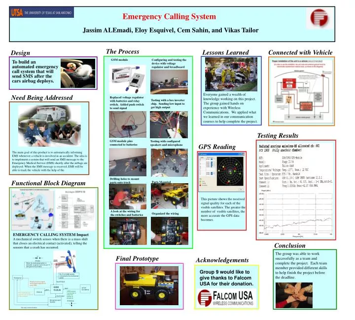
Emergency Calling System Jassim ALEmadi, Eloy Esquivel, Cem Sahin, and Vikas Tailor The Process Lessons Learned Connected with Vehicle Design GSM module Configuring and testing the device with voltage regulator and breadboard To build an automated emergency call system that will send SMS after the cars airbag deploys. Everyone gained a wealth of knowledge working on this project. The group gained hands on experience with Wireless Communications. We applied what we learned in our communication courses to help complete the project. Need Being Addressed Replaced voltage regulator with batteries and relay switch. Added push switch to send signal Testing with a hex inverter chip. Sending low input to get high output Testing Results GSM module pins connected to batteries Testing with configured speakers and microphone GPS Reading The main goal of this product is to automatically informing EMS whenever a vehicle is involved in an accident. The idea is to implement a system that will send an SMS message to the Emergency Medical Service (EMS) shortly after the airbags are deployed. When the SMS message is received, EMS will be able to track the vehicle with the help of the Drilling holes to mount parts onto truck Functional Block Diagram Parts Mounted This picture shows the received signal quality for each of the visible satellites. The greater the number of visible satellites, the more accurate the GPS data becomes. A look at the wiring for the switches and batteries Organized the wiring EMERGENCY CALLING SYSTEM Impact A mechanical switch senses when there is a mass shift that closes an electrical contact (activated), telling the sensors that a crash has occurred. Conclusion The group was able to work successfully as a team and complete the project. Each team member provided different skills to help finish the project before the deadline. Final Prototype Acknowledgements (PUSH) When the mechanical switch is activated, a signal is sent into pin 10 and goes to the module Group 9 would like to give thanks to Falcom USA for their donation. Pin 10 of GSM module connected to the mechanical switch Emergency Module receives signal and initiates algorithm to send SMS. Input/Output GSM module 12 Volt Car battery input input GSM module is powered on when the ignition is turned on Antenna GPS readings give Latitude and Longitude of the accident Input/output Microphone and Speaker (TOGGLE) Two-way communication